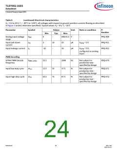
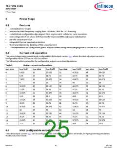
TLD7002-16ES
Datasheet
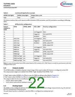
5 General Purpose Input (GPI)
5
General Purpose Input (GPI)
Overview and features
5.1
The device provides two general purpose input pins GPIN0 and GPIN1. The GPINs can be used as
•
•
digital input for direct drive feature to operate the device without the HSLI interface
analog inputs connected to the internal ADC multiplexer for external NTC/PTC measurements
Accepted input signals for the direct drive feature can be either static voltage level or PWM decoded duty cycle
5.2
Digital Input
The GPINn pins integrate an internal pull-down function when set as digital input, where the pull-down current is
defined by IPD
.
The digital input is set by default on GPIN0 and disabled on GPIN1. If the GPINn is used as analog input, the pull-down
current is disabled as described in Chapter 5.5.
If GPINn is set as digital input it can be used to move the device in active mode. This is valid also if no outputs
are mapped to GPINn. An activation request is either a static input high voltage level (Vih) or a PWM input high duty
cycle (dc_hi) with GPINn set as digital input.
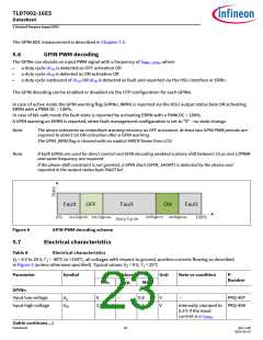
5.3
Direct drive
The direct drive function can be used to operate the device without the HSLI interface. A valid PWM signal on GPIN
overwrites the HSLI request. One or both inputs drive one to all power output channels defined with a GPINn to OUTn
mapping stored in the OTP.
GPIN0OUTn MAP - Group0
GPIN1OUTn MAP - Group1
0b aaaa aaaa aaaa aaaa
0b bbbb bbbb bbbb bbbb
Definition for a,b
"0" ... input is not mapped to the corresponding power output stage
"1" ... input is mapped to the corresponding power output stage
Each GPIN is mapped to one set of 16 duty cycle configuration with a resolution of 8-bit. The configuration is stored in
the OTP. The GPIN0 duty cycle configuration shares the fail-safe duty cycle configuration.
In case two GPINs are mapped to the same OUTn both GPINs demands are combined by a logical OR.
A GPIN1 ON demand has higher priority than a GPIN0 ON demand to resolve the duty cycle configuration conflict.
Application example:
GPIN1 is used to active a stop light function, where OUTn is configured to 100ꢀ duty cycle
GPIN0 is used to active a tail light function, where OUTn is configured to 6ꢀ duty cycle
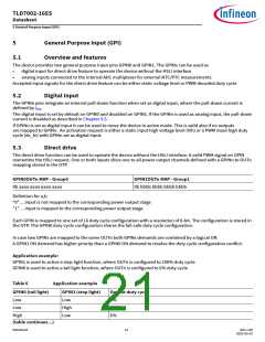
Table 6
Application example
GPIN0 (tail light)
GPIN1 (stop light)
Output duty cycle
Low
Low
Low
High
Low
0ꢀ
100ꢀ
6ꢀ
High
(table continues...)
Datasheet
21
Rev.1.00
2022-05-03

 INFINEON [ Infineon ]