S29GL01GP
S29GL512P
S29GL256P
S29GL128P
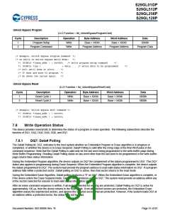
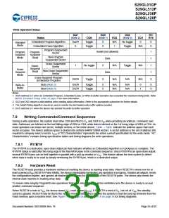
Write Operation Status
DQ7
(Note 2)
DQ5
(Note 1)
DQ2
(Note 2)
RY/
BY#
Status
DQ6
DQ3
N/A
1
DQ1
0
Embedded Program Algorithm
Embedded Erase Algorithm
Program-Suspended
DQ7#
0
Toggle
Toggle
0
0
No toggle
Toggle
0
Standard
Mode
N/A
0
Invalid (not allowed)
Data
1
1
1
1
0
Program
Suspend
Mode
Program-
Sector
Suspend
Non-Program
Suspended Sector
Read
Erase-Suspended
Sector
1
No toggle
Toggle
0
N/A
Toggle
N/A
N/A
N/A
Erase-
Suspend
Read
Erase
Suspend
Mode
Non-EraseSuspended
Sector
Data
Erase-Suspend-Program
(Embedded Program)
DQ7#
0
N/A
Busy (Note 3)
Abort (Note 4)
DQ7#
DQ7#
Toggle
Toggle
0
0
N/A
N/A
N/A
N/A
0
1
0
0
Write-to-
Buffer
Notes
1. DQ5 switches to 1 when an Embedded Program, Embedded Erase, or Write-to-Buffer operation has exceeded the maximum timing limits. Refer
toDQ5: Exceeded Timing Limits on page 35 for more information.
2. DQ7 and DQ2 require a valid address when reading status information. Refer to the appropriate subsection for further details.
3. The Data# Polling algorithm should be used to monitor the last loaded write-buffer address location.
4. DQ1 switches to 1 when the device has aborted the write-to-buffer operation
7.9
Writing Commands/Command Sequences
During a write operation, the system must drive CE# and WE# to VIL and OE# to VIH when providing an address, command, and
data. Addresses are latched on the last falling edge of WE# or CE#, while data is latched on the 1st rising edge of WE# or CE#. An
erase operation can erase one sector, multiple sectors, or the entire device. Table – Table indicate the address space that each
sector occupies. The device address space is divided into uniform 64KW/128KB sectors. A sector address is the set of address bits
required to uniquely select a sector. ICC2 in “DC Characteristics” represents the active current specification for the write mode. “AC
Characteristics” contains timing specification tables and timing diagrams for write operations.
7.9.1
RY/BY#
The RY/BY# is a dedicated, open-drain output pin that indicates whether an Embedded Algorithm is in progress or complete. The
RY/BY# status is valid after the rising edge of the final WE# pulse in the command sequence. Since RY/BY# is an open-drain output,
several RY/BY# pins can be tied together in parallel with a pull-up resistor to VCC. This feature allows the host system to detect
when data is ready to be read by simply monitoring the RY/BY# pin, which is a dedicated output.
7.9.2
Hardware Reset
The RESET# input provides a hardware method of resetting the device to reading array data. When RESET# is driven low for at
least a period of tRP (RESET# Pulse Width), the device immediately terminates any operation in progress, tristates all outputs, resets
the configuration register, and ignores all read/write commands for the duration of the RESET# pulse. The device also resets the
internal state machine to reading array data.
To ensure data integrity Program/Erase operations that were interrupted should be reinitiated once the device is ready to accept
another command sequence.
When RESET# is held at VSS, the device draws VCC reset current (ICC5). If RESET# is held at VIL, but not at VSS, the standby
current is greater. RESET# may be tied to the system reset circuitry which enables the system to read the boot-up firmware from the
Flash memory upon a system reset. See Figure 11.7 on page 55 and Figure 11.8 on page 56 for timing diagrams.
Document Number: 002-00886 Rev. *B
Page 35 of 83

 INFINEON [ Infineon ]