S29GL01GP
S29GL512P
S29GL256P
S29GL128P
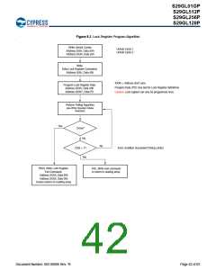
8.1
Lock Register
As shipped from the factory, all devices default to the persistent mode when power is applied, and all sectors are unprotected,
unless otherwise chosen through the DYB ordering option (see Ordering Information on page 4). The device programmer or host
system must then choose which sector protection method to use. Programming (setting to “0”) any one of the following two one-time
programmable, non-volatile bits locks the part permanently in that mode:
Lock Register Persistent Protection Mode Lock Bit (DQ1)
Lock Register Password Protection Mode Lock Bit (DQ2)
Lock Register
DQ15-3
DQ2
DQ1
DQ0
Password Protection Mode
Lock Bit
Persistent Protection Mode
Lock Bit
Secured Silicon Sector
Protection Bit
Don’t Care
For programming lock register bits refer to Table on page 67 and Table on page 71.
Notes
1. If the password mode is chosen, the password must be programmed before setting the corresponding lock register bit.
2. After the Lock Register Bits Command Set Entry command sequence is written, reads and writes for Sector 0 are
disabled, while reads from other sectors are allowed until exiting this mode.
3. If both lock bits are selected to be programmed (to zeros) at the same time, the operation aborts.
4. Once the Password Mode Lock Bit is programmed, the Persistent Mode Lock Bit is permanently disabled, and no
changes to the protection scheme are allowed. Similarly, if the Persistent Mode Lock Bit is programmed, the Password
Mode is permanently disabled.
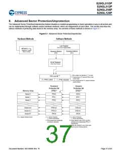
After selecting a sector protection method, each sector can operate in any of the following three states:
1. Constantly locked. The selected sectors are protected and can not be reprogrammed unless PPB lock bit is cleared via a
password, hardware reset, or power cycle.
2. Dynamically locked. The selected sectors are protected and can be altered via software commands.
3. Unlocked. The sectors are unprotected and can be erased and/or programmed.
These states are controlled by the bit types described in Section 8.2–Section 8.5.
8.2
Persistent Protection Bits
The Persistent Protection Bits are unique and nonvolatile for each sector and have the same endurances as the Flash memory.
Preprogramming and verification prior to erasure are handled by the device, and therefore do not require system monitoring.
Notes
1. Each PPB is individually programmed and all are erased in parallel.
2. While programming PPB for a sector, array data can be read from any other sector, except Sector 0 (used for Data#
Polling) and the sector in which sector PPB is being programmed.
3. Entry command disables reads and writes for the sector selected.
4. Reads within that sector return the PPB status for that sector.
5. All Reads must be performed using the read mode.
6. The specific sector address (A25-A16 GL01GP, A24-A16 GL512P, A23-A16 GL256P, A22-A16 GL128P) are written at the
same time as the program command.
7. If the PPB Lock Bit is set, the PPB Program or erase command does not execute and times-out without programming or
erasing the PPB.
8. There are no means for individually erasing a specific PPB and no specific sector address is required for this operation.
Document Number: 002-00886 Rev. *B
Page 38 of 83

 INFINEON [ Infineon ]