PEB 2091
PEF 2091
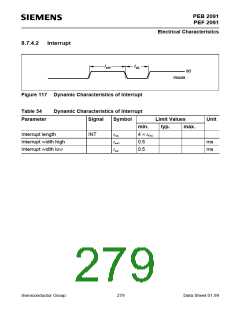
Electrical Characteristics
T
DCL
tr
tf
DCL
FSC
twH
twL
tdF
tsF
twFH
tdDF
Data Valid
DOUT
DIN
tdDC
thD
Data Valid
tsD
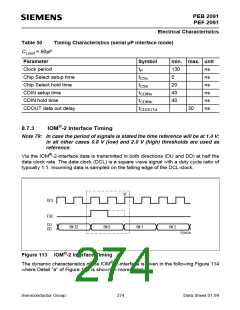
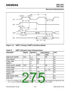
Figure 114 IOM®-2 Timing of IOM®-2 Interface (Detail)
Table 51
IOM®-2 Dynamic Input Characteristics
Parameter
Signal
Symbol
Limit Values
Unit
min.
max.
Data clock rise/fall
Clock period
DCL
tR, tF
60
ns
ns
TDCL
200
Pulse width
high/low
twH
twL
53
53
ns
ns
Frame synch. rise/fall
Frame setup
FSC
tR, tF
tsF
60
ns
ns
ns
ns
30
Frame hold
tdF
twL – 30
Frame width
high/low1)
twFH
twFL
100
2 × TDCL
Data sample delay
Data hold
DIN
tsD
thD
twH + 20
ns
ns
50
®
1) This is in according to the IOM -2-timing specification. For correct functional operation the high period must
be 1 × T
for superframe markers and at least 2 × T
for non-superframe markers
DCL
DCL
Semiconductor Group
275
Data Sheet 01.99

 INFINEON [ Infineon ]