CoolSET®-F3R
ICE3BR0665JF
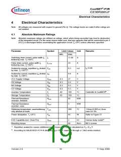
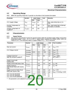
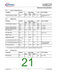
Electrical Characteristics
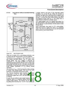
4.3.5
Control Unit
Parameter
Symbol
Limit Values
Unit
Test Condition
min.
typ.
max.
Clamped VBA voltage during
Normal Operating Mode
VBAclmp
VBKC3
0.85
0.9
0.95
4.15
4.72
1.31
3.74
3.22
21.7
V
V
V
V
V
V
V
VFB = 4V
Blanking time voltage limit for
Comparator C3
3.85
4.28
1.13
3.45
2.97
4.00
4.50
1.22
3.60
3.10
20.7
Over Load & Open Loop Detection VFBC4
Limit for Comparator C4
Active Burst Mode Level for
Comparator C5
VFBC5
Active Burst Mode Level for
Comparator C6a
VFBC6a
VFBC6b
After Active Burst
Mode is entered
Active Burst Mode Level for
Comparator C6b
After Active Burst
Mode is entered
Overvoltage Detection Limit for
Comparator C1
VVCCOVP1 19.6
VFB = 5V
Overvoltage Detection Limit for
Comparator C2
VVCCOVP2 25.0
25.5
0.33
13.5
26.3
0.42
16.1
V
Auto-restart Enable level at BA pin VAE
0.25
10.1
V
for Comparator C9
Charging current at BA pin
Thermal Shutdown1)
IBK
µA
Charge starts after the
built-in 20ms blanking
time elapsed
TjSD
tBK
130
-
140
20
150
-
°C
Controller
Built-in Blanking Time for
Overload Protection or enter
Active Burst Mode
ms
without external
capacitor at BA pin
Inhibit Time for Auto-Restart
enable function during start up
tIHAE
tSpike
-
-
1.0
30
-
-
ms
Count when VCC>18V
Spike Blanking Time before Auto
Restart Protection
µs
1)
The parameter is not subjected to production test - verified by design/characterization
Note: The trend of all the voltage levels in the Control Unit is the same regarding the deviation except VVCCOVP
and VVCCPD
Version 2.0
22
11 Sep 2008

 INFINEON [ Infineon ]