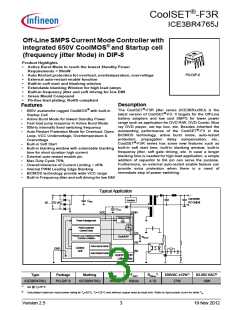
CoolSET®-F3R
ICE3BR4765J
Pin Configuration and Functionality
1
Pin Configuration and Functionality
1.1
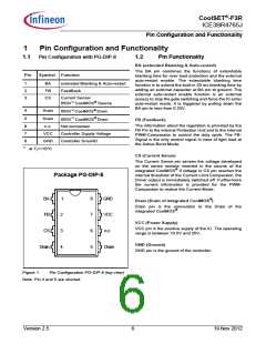
Pin Configuration with PG-DIP-8
1.2
Pin Functionality
BA (extended Blanking & Auto-restart)
The BA pin combines the functions of extendable
blanking time for over load protection and the external
auto-restart enable. The extendable blanking time
function is to extend the built-in 20 ms blanking time by
adding an external capacitor at BA pin to ground. The
external auto-restart enable function is an external
access to stop the gate switching and force the IC enter
auto-restart mode. It is triggered by pulling down the
BA pin to less than 0.33V.
Pin
Symbol Function
1
2
3
BA
FB
CS
extended Blanking & Auto-restart
FeedBack
Current Sense/
650V1) CoolMOS® Source
650V1) CoolMOS® Drain
4
5
Drain
Drain
650V1) CoolMOS® Drain
Not connected
FB (Feedback)
The information about the regulation is provided by the
FB Pin to the internal Protection Unit and to the internal
PWM-Comparator to control the duty cycle. The FB-
Signal is the only control signal in case of light load at
the Active Burst Mode.
6
7
n.c.
VCC
GND
Controller Supply Voltage
Controller GrouND
8
1)
at Tj=110°C
CS (Current Sense)
The Current Sense pin senses the voltage developed
on the series resistor inserted in the source of the
integrated CoolMOS® If voltage in CS pin reaches the
internal threshold of the Current Limit Comparator, the
Driver output is immediately switched off. Furthermore
the current information is provided for the PWM-
Comparator to realize the Current Mode.
Package PG-DIP-8
BA
FB
1
8
7
6
5
GND
VCC
n.c.
Drain (Drain of integrated CoolMOS®)
Drain pin is the connection to the Drain of the
integrated CoolMOS®.
2
VCC (Power Supply)
VCC pin is the positive supply of the IC. The operating
range is between 10.5V and 25V.
CS
3
4
GND (Ground)
Drain
Drain
GND pin is the ground of the controller.
Figure 1
Pin Configuration PG-DIP-8 (top view)
Note: Pin 4 and 5 are shorted
Version 2.5
6
19 Nov 2012

 INFINEON [ Infineon ]