Quasi-Resonant PWM Controller
ICE2QS01
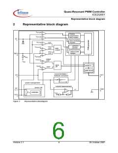
Functional Description
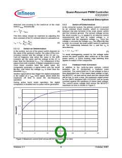
controller is implemented to avoid mistriggering by the limited between 1 and 7. If the counter tends to count
ring after MOSFET is turned off. Functionality of these beyond this range, the attempt is ignored.
parts is described as in the following.
In normal case, the up/down counter can only be
changed by one each time at the clock period of 48ms.
However, to ensure a fast response to sudden load
3.3.1.1 Up/down Counter
The up/down counter stores the number of zero increase, the counter is set to 1 in the following
crossing to be ignored before the main power switch is switching period after the regulation voltage vREG
switched on after demagnetisation of the transformer. exceeds the threshold VRM
.
This value is a function of the regulation voltage, which
contains information about the output power. 3.3.1.2
Zero-Crossing Counter and Ringing
Suppression Time Controller
Generally, a high output power results in a high
regulation voltage. According to this information, the
value in the up/down counter is changed to a low value
in case of high regulation voltage, and to a high value
in case of low regulation voltage. In ICE2QS01, the
lowest value of the counter is 1 and the highest 7.
Following text explains how the up/down counter value
In the system, the voltage from the auxiliary winding is
applied to the zero-crossing pin through a RC network,
which provides a time delay to the voltage from the
auxiliary winding. Internally, this pin is connected to a
clamping network, a zero-crossing detector, an output
overvoltage (OP OVP) detector and
suppression time controller.
a ringing
changes in responding to the regulation voltage vREG
.
The regulation voltage vREG is internally compared with
three thresholds VRL, VRH and VRM. According to the
results, the value in the up/down counter is changed,
which is summarised in Table 1 and Figure 4
respectively.
During on-state of the power switch a negative voltage
applies to the ZC pin. Through the internal clamping
network, the voltage at the pin is clamped to certain
level. However, it is highly recommended that a fast-
recovery diode Dzc is added to block the negative
voltage when the power switch is on. This is because
the device in MOS technology is sensitive to negative
voltage.
The voltage at the ZC pin vZC is compared with the
threshold VZCT1. Once the voltage vZC crosses the
threshold at its falling edge, a pulse is generated which
is fed to the zero-crossing counter and the counter
value increases by 1.
After MOSFET is turned on, there will be some
oscillation on VDS, which will also appear on the voltage
on ZC pin. To avoid the MOSFET is turned on
mistriggerred by such oscillation, a ringing suppression
timer is implemented. The time is dependent on the
voltage vZC. When the voltage vZC is lower than the
threshold VZCT2, a longer preset time applies, while a
shorter time is set when the voltage vZC is higher than
the threshold.
The voltage vZC is used for the output overvoltage
protection, as well. Once the voltage at this pin is
higher than the threshold VOPOVP during off-time of the
main switch, the IC is latched off after a fixed blanking
time.
Table 1
vREG
Operation of the up/down counter
up/down counter
action
Count upwards till
Always lower than VRL
7
Once higher than VRL, but
always lower than VRH
Once higher than VRH, but
always lower than VRM
Stop counting, no
value changing
Count downwards
till 1
Set up/down
counter to 1
Once higher than VRM
clock
T=48ms
t
VFB
VRM
VRH
VRL
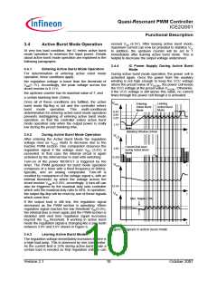
To achieve the switch-on at voltage valley, the voltage
from the auxiliary winding is fed to a time delay network
(the RC network consists of Dzc, Rzc1, Rzc2 and Czc as
shown in typical application circuit) before it is applied
to the zero-crossing detector through the ZC pin. The
needed time delay to the main oscillation signal ∆t
should be approximately one fourth of the oscillation
period (by transformer primary inductor and drain-
source capacitor) minus the propagation delay from the
t
1
Case 1
Case 2
Case 3
4
2
7
5
3
7
6
4
7
6
4
7
6
4
7
6
4
7
5
3
6
4
2
5
3
1
4
1
1
1
Figure 4
Up/down counter operation
According to the comparison results the up/down
counter counts upwards, keeps unchanged or counts
downwards. However, the value in up/down counter is
Version 2.1
8
October 2007

 INFINEON [ Infineon ]