Quasi-Resonant PWM Controller
ICE2QS01
Functional Description
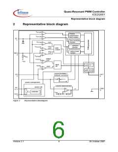
drops (Phase II). Once the output voltage is high
enough, the VCC capacitor receives then energy from
the auxiliary winding from the time point t2 on. The VCC
then will reach a constant value depending on output
load.
3
Functional Description
3.1
VCC Pre-Charging and Typical
VCC Voltage During Start-up
Since there is a VCC undervoltage protection, the
capacitance of the VCC capacitor should be selected to
be high enough to ensure that enough energy is stored
in the VCC capacitor so that the VCC voltage will never
touch the VCC under voltage protection threshold
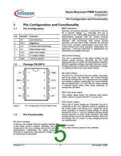
In the controller ICE2QS01, a power cell is integrated.
As shown in Figure 2, the power cell consists of a high
voltage device and a controller, whereby the high
voltage device is controlled by the controller. The
power cell provides a pre-charging of the VCC
capacitor till VCC voltage reaches the VCC turned-on
threshold VVCCon and the IC begins to operate, while it
may keep the VCC voltage at a constant value during
burst mode operation when the output voltage is pulled
down or the power from the auxiliary winding is not
enough, or when the IC is latched off in certain
protection mode.
V
VCCUVP before the output voltage is built up. Therefore,
the capacitance should fulfill the following requirement:
I
VCCop ⋅ (t2 – t1)
C
vcc ≥ ------------------------------------------------
[2]
VVCCon – VVCCUVP
with IVCCop the operating current of the controller.
3.2
Soft-start
Once the mains input voltage is applied, a rectified
voltage shows across the capacitor Cbus. The high
voltage device provides a current to charge the VCC
capacitor Cvcc. Before the VCC voltage reaches a
certain value, the amplitude of the current through the
high voltage device is only determined by its channel
resistance and can be as high as several mA. After the
VCC voltage is high enough, the controller controls the
high voltage device so that a constant current around
1mA is provided to charge the VCC capacitor further,
until the VCC voltage exceeds the turned-on threshold
At the time t1, the IC begins to operate with a soft-start.
By this soft-start the switching stresses for the switch,
diode and transformer are minimised. The soft-start
implemented in the ICE2QS01 is a digital time-based
function. The preset soft-start time is 24ms with 8
steps. The internal reference for the regulation voltage
begins at 1.35V and with an increment of 0.35V for
each following step.
V
VCCon. As shown as the time phase I in Figure 3, the
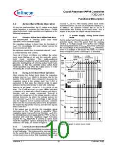
3.3
Normal Operation
VCC voltage increase near linearly.
The PWM section of the IC can be divided into two
main portions: PWM controller for normal operation
and PWM controller for burst mode operation. The
PWM controller for normal operation will be described
in the following paragraphs, while the PWM controller
for burst mode operation will be discussed in the next
section.
VCC
i
ii
iii
VVCCon
VVCCUVP
The PWM controller for normal operation consists of
digital signal processing circuit including an up/down
counter, a zero-crossing counter (ZC-counter) and a
comparator, and analog circuit including a current
measurement unit and a comparator. The switch-on
and -off time point is determined by the digital circuit
and the analog circuit, respectively. As input
information for the switch-on determination, the zero-
crossing input signal and the value of the up/down
counter are needed, while the feedback signal vREG
and the current sensing signal vCS are necessary for
the switch-off determination. Details about the
operation of the PWM controller in normal operation
are illustrated in the following paragraphs.
t2
VCC voltage at start up
The time taking for the VCC pre-charging can then be
approximately calculated as:
t
t1
Figure 3
V
VCCon ⋅ Cvcc
t1 = ---------------------------------
IVCCch arge2
[1]
where IVCCcharge2 is the charging current from the power
cell which is 1.05mA, typically.
Exceeds the VCC voltage the turned-on threshold
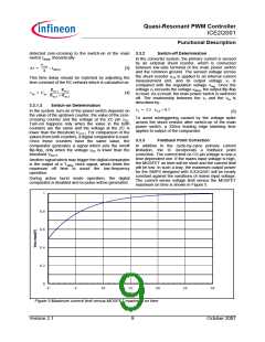
3.3.1
Switch-on Determination
V
VCCon of at time t1, the power cell is switched off, and
the IC begins to operate with a soft-start. Due to power
consumption of the IC and the fact that still no energy
from the auxiliary winding to charge the VCC capacitor
before the output voltage is built up, the VCC voltage
As mentioned above, the digital signal processing
circuit consists of an up/down counter, a zero-crossing
counter and a comparator. A ringing suppression time
Version 2.1
7
October 2007

 INFINEON [ Infineon ]