TechnischeꢀInformationꢀ/ꢀTechnicalꢀInformation
IGBT-Modul
IGBT-Module
DDB6U134N16RR_B11
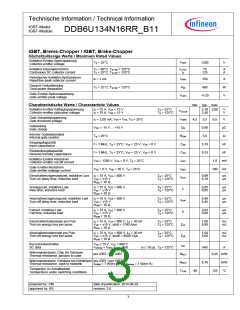
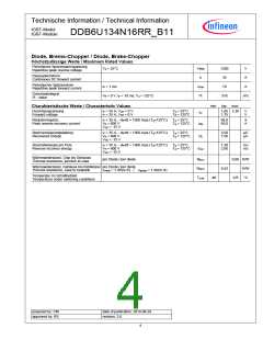
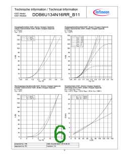
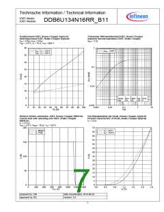
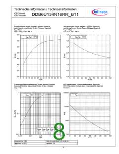
IGBT,ꢀBrems-Chopperꢀ/ꢀIGBT,ꢀBrake-Chopper
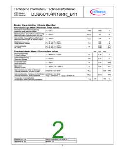
HöchstzulässigeꢀWerteꢀ/ꢀMaximumꢀRatedꢀValues
Kollektor-Emitter-Sperrspannung
Collector-emitterꢀvoltage
Tvj = 25°C
VCES
ꢀ
ꢀ
ꢀ
ꢀ
ꢀ
1200
ꢀ
ꢀ
ꢀ
V
Kollektor-Dauergleichstrom
ContinuousꢀDCꢀcollectorꢀcurrent
TC = 80°C, Tvj max = 125°C
TC = 25°C, Tvj max = 125°C
IC nom
IC
75
125
A
A
PeriodischerꢀKollektor-Spitzenstrom
Repetitiveꢀpeakꢀcollectorꢀcurrent
tP = 1 ms
ICRM
Ptot
150
400
A
Gesamt-Verlustleistung
Totalꢀpowerꢀdissipation
TC = 25°C, Tvj max = 125°C
ꢀ W
Gate-Emitter-Spitzenspannung
Gate-emitterꢀpeakꢀvoltage
VGES
+/-20
ꢀ
V
CharakteristischeꢀWerteꢀ/ꢀCharacteristicꢀValues
min. typ. max.
Kollektor-Emitter-Sättigungsspannung
Collector-emitterꢀsaturationꢀvoltage
IC = 75 A, VGE = 15 V
IC = 75 A, VGE = 15 V
Tvj = 25°C
Tvj = 125°C
2,10 2,60
2,40
V
V
VCE sat
VGEth
QG
Gate-Schwellenspannung
Gateꢀthresholdꢀvoltage
IC = 3,00 mA, VCE = VGE, Tvj = 25°C
VGE = -15 V ... +15 V
4,5
5,5
0,80
5,0
6,5
V
µC
Ω
Gateladung
Gateꢀcharge
InternerꢀGatewiderstand
Internalꢀgateꢀresistor
Tvj = 25°C
RGint
Cies
Eingangskapazität
Inputꢀcapacitance
f = 1 MHz, Tvj = 25°C, VCE = 25 V, VGE = 0 V
f = 1 MHz, Tvj = 25°C, VCE = 25 V, VGE = 0 V
VCE = 1200 V, VGE = 0 V, Tvj = 25°C
VCE = 0 V, VGE = 20 V, Tvj = 25°C
5,10
0,33
nF
nF
Rückwirkungskapazität
Reverseꢀtransferꢀcapacitance
Cres
ICES
IGES
td on
Kollektor-Emitter-Reststrom
Collector-emitterꢀcut-offꢀcurrent
1,0 mA
100 nA
Gate-Emitter-Reststrom
Gate-emitterꢀleakageꢀcurrent
Einschaltverzögerungszeit,ꢀinduktiveꢀLast
Turn-onꢀdelayꢀtime,ꢀinductiveꢀload
IC = 75 A, VCE = 600 V
VGE = ±15 V
Tvj = 25°C
Tvj = 125°C
0,09
0,10
µs
µs
RGon = 10 Ω
Anstiegszeit,ꢀinduktiveꢀLast
Riseꢀtime,ꢀinductiveꢀload
IC = 75 A, VCE = 600 V
VGE = ±15 V
RGon = 10 Ω
Tvj = 25°C
Tvj = 125°C
0,05
0,05
µs
µs
tr
td off
tf
Abschaltverzögerungszeit,ꢀinduktiveꢀLast
Turn-offꢀdelayꢀtime,ꢀinductiveꢀload
IC = 75 A, VCE = 600 V
VGE = ±15 V
RGoff = 10 Ω
Tvj = 25°C
Tvj = 125°C
0,40
0,45
µs
µs
Fallzeit,ꢀinduktiveꢀLast
Fallꢀtime,ꢀinductiveꢀload
IC = 75 A, VCE = 600 V
VGE = ±15 V
Tvj = 25°C
Tvj = 125°C
0,03
0,06
µs
µs
RGoff = 10 Ω
EinschaltverlustenergieꢀproꢀPuls
Turn-onꢀenergyꢀlossꢀperꢀpulse
IC = 75 A, VCE = 600 V, LS = 30 nH
VGE = ±15 V, di/dt = 1700 A/µs
RGon = 10 Ω
Tvj = 25°C
Tvj = 125°C
7,00
8,80
mJ
mJ
Eon
Eoff
AbschaltverlustenergieꢀproꢀPuls
Turn-offꢀenergyꢀlossꢀperꢀpulse
IC = 75 A, VCE = 600 V, LS = 30 nH
VGE = ±15 V, du/dt = 4600 V/µs
RGoff = 10 Ω
Tvj = 25°C
Tvj = 125°C
5,50
8,60
mJ
mJ
Kurzschlußverhalten
SCꢀdata
VGE ≤ 15 V, VCC = 900 V
VCEmax = VCES -LsCE ·di/dt
ISC
tP ≤ 10 µs, Tvj = 125°C
540
A
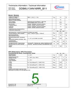
Wärmewiderstand,ꢀChipꢀbisꢀGehäuse
Thermalꢀresistance,ꢀjunctionꢀtoꢀcase
proꢀIGBTꢀ/ꢀperꢀIGBT
RthJC
RthCH
Tvj op
0,25 K/W
Wärmewiderstand,ꢀGehäuseꢀbisꢀKühlkörper proꢀIGBTꢀ/ꢀperꢀIGBT
Thermalꢀresistance,ꢀcaseꢀtoꢀheatsink
0,16
K/W
λPasteꢀ=ꢀ1ꢀW/(m·K)ꢀꢀꢀ/ꢀꢀꢀꢀλgreaseꢀ=ꢀ1ꢀW/(m·K)
TemperaturꢀimꢀSchaltbetrieb
Temperatureꢀunderꢀswitchingꢀconditions
-40
125
°C
preparedꢀby:ꢀCM
approvedꢀby:ꢀRS
dateꢀofꢀpublication:ꢀ2014-08-29
revision:ꢀ3.0
3

 INFINEON [ Infineon ]