High Current PN Half Bridge
BTS 7960
Block Description and Characteristics
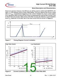
IN pin are ignored. However, the INH pin can still be used to switch both MOSFETs off.
After tCLS the switches return to their initial setting. The error signal at the IS pin is reset
after 2 * tCLS. Unintentional triggering of the current limitation by short current spikes
(e.g. inflicted by EMI coming from the motor) is suppressed by internal filter circuitry. Due
to thresholds and reaction delay times of the filter circuitry the effective current limitation
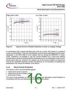
level ICLx depends on the slew rate of the load current dI/dt as shown in Figure 8
IL
tCLS
ICLx
ICLx0
t
Figure 7
Timing Diagram Current Limitation
High Side Switch
Low SideSwitch
80
75
70
65
60
55
80
75
70
65
60
Tj = -40°C
Tj = 150°C
Tj = 25°C
ICLH0
55
Tj = -40°C
Tj = 25°C
ICLL0
50
50
45
40
35
45
40
35
Tj = 150°C
0
500
1000
1500
2000
0
500
1000
1500
2000
dIL/dt [A/ms]
dIL/dt[A/ms]
Figure 8
Current Limitation Level vs. Current Slew Rate dI/dt
Data Sheet
14
Rev. 1.1, 2004-12-07

 INFINEON [ Infineon ]