BTS7012-2EPA
PROFET™ +2 12V
Power Supply
6
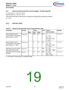
Power Supply
The BTS7012-2EPA is supplied by VS, which is used for the internal logic as well as supply for the power output
stages. VS has an undervoltage detection circuit, which prevents the activation of the power output stages and
diagnosis in case the applied voltage is below the undervoltage threshold.
6.1
Operation Modes
BTS7012-2EPA has the following operation modes:
•
•
•
Sleep mode
Active mode
Stand-by mode
The transition between operation modes is determined according to these variables:
•
•
Logic level at INn pins
Logic level at DEN pin
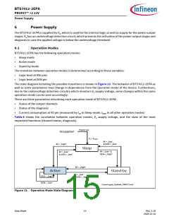
The state diagram including the possible transitions is shown in Figure 13. The behavior of BTS7012-2EPA as
well as some parameters may change in dependence from the operation mode of the device. Furthermore,
due to the undervoltage detection circuitry which monitors VS supply voltage, some changes within the same
operation mode can be seen accordingly.
There are three parameters describing each operation mode of BTS7012-2EPA:
•
•
•
Status of the output channels
Status of the diagnosis
Current consumption at VS pin (measured by IVS in Sleep mode, IGND in all other operative modes)
Table 8 shows the correlation between operation modes, VS supply voltage, and the state of the most
important functions (channel status, diagnosis).
Power-up
Unsupplied
VS > VS(OP)
IN = „low“
& DEN = „low“
IN = „high“
Sleep
IN = „low“ &
DEN = „high“
IN = „low“
& DEN = „low“
IN = „high“
Active
DEN = „high“
Stand-by
IN = „low“
& DEN = „high“
DEN = „low“
PowerSupply_OpMode_PROFET.emf
Figure 13 Operation Mode State Diagram
Data Sheet
15
Rev. 1.10
2020-12-14

 INFINEON [ Infineon ]