BTS7012-2EPA
PROFET™ +2 12V
Logic Pins
5
Logic Pins
The device has 4 digital pins for direct control.
5.1
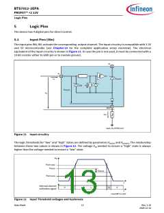
Input Pins (INn)
The input pins IN0, IN1 activate the corresponding output channel. The input circuitry is compatible with 3.3V
and 5V microcontroller (see Chapter 10 for the complete application setup overview). The electrical
equivalent of the input circuitry is shown in Figure 11. In case the pin is not used, it must be connected with a
10 kΩ resistor either to GND pin or to module ground.
VS
IN
VS(CLAMP)
IDI
IDI
ESD
VDI(CLAMP)
VDI
GND
IGND
Input_IN_INTDIO.emf
Figure 11 Input circuitry
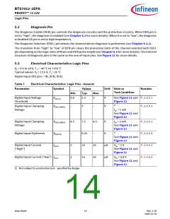
The logic thresholds for “low” and “high” states are defined by parameters VDI(TH) and VDI(HYS). The relationship
between these two values is shown in Figure 12. The voltage VIN needed to ensure a “high” state is always
higher than the voltage needed to ensure a “low” state.
VDI
VDI(TH ),MAX
VDI(TH)
VDI(HYS)
VDI(TH ),MIN
t
Internal channel
activation signal
0
x
1
x
0
t
Input_VDITH_2.emf
Figure 12 Input Threshold voltages and hysteresis
Data Sheet
13
Rev. 1.10
2020-12-14

 INFINEON [ Infineon ]