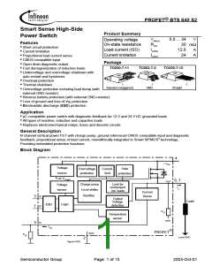
BTS 640 S2
Parameter and Conditions
Symbol
Values
typ max
Unit
at Tj = 25 °C, V = 12 V unless otherwise specified
bb
min
Operating Parameters
Operating voltage 5)
Undervoltage shutdown
Undervoltage restart
T =-40...+150°C: Vbb(on)
5.0
3.2
--
--
--
34
V
V
V
j
T =-40...+150°C: Vbb(under)
j
5.0
T =-40...+25°C: Vbb(u rst)
4.5
5.5
6.0
j
T =+150°C:
j
Undervoltage restart of charge pump
see diagram page 13
T =-40...+25°C: Vbb(ucp)
--
--
4.7
--
6.5
7.0
V
V
j
T =25...150°C:
j
Undervoltage hysteresis
∆Vbb(under)
--
0.5
--
∆V
bb(under)
= V
- V
bb(u rst) bb(under)
Overvoltage shutdown
Overvoltage restart
T =-40...+150°C: Vbb(over)
34
33
--
--
--
1
43
--
V
V
V
V
j
T =-40...+150°C: Vbb(o rst)
j
Overvoltage hysteresis
Overvoltage protection6)
T =-40...+150°C: ∆Vbb(over)
j
--
T =-40°C: Vbb(AZ)
41
43
--
47
--
52
j
I =40 mA
bb
T =+25...+150°C
j
Standby current (pin 4)
V
=0
Tj=-40...+25°C: Ibb(off)
Tj= 150°C:
--
--
4
12
15 µA
25
IN
IL(off)
--
--
10 µA
Off state output current (included in Ibb(off)
)
,
=-40...+150°C
:
VIN=0
Tj
7)
IGND
--
1.2
3
mA
Operating current (Pin 2) , V =5 V
IN
5)
At supply voltage increase up to V = 4.7 V typ without charge pump, V
≈V - 2 V
bb
bb
OUT
6)
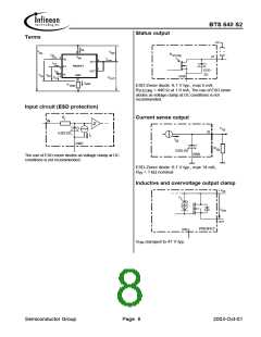
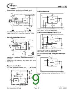
Supply voltages higher than Vbb(AZ) require an external current limit for the GND and status pins (a 150 Ω
resistor in the GND connection is recommended). See also V
in table of protection functions and
ON(CL)
circuit diagram page 9.
7)
Add I , if I > 0, add I , if V >5.5 V
ST
ST
IN
IN
Semiconductor Group
Page 4
2003-Oct-01

 INFINEON [ Infineon ]