PROFET Data sheet BTS 6163 D
Thermal Characteristics
Parameter and Conditions
Symbol
Values
Unit
min
--
typ
max
1.1
--
RthJC
chip - case:
K/W
--
80
Thermal resistance
junction - ambient (free air): RthJA
SMD version, device on PCB :
--
--
6)
45
55
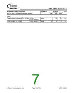
Electrical Characteristics
Parameter and Conditions
Symbol
Values
Unit
at T= 25, V = 24 V unless otherwise specified
bb
j
min
typ
max
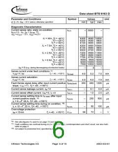
Load Switching Capabilities and Characteristics
On-state resistance (pin 3 to pin 1,5)
VIN= 0, Vbb= 5.5V, IL = 7.5 A
T=25 °C: RON
T=150 °C:
j
--
--
19
38
25
50
mΩ
j
VIN= 0, Vbb= 12..24V, IL = 7.5 A
T=25 °C:
T=150 °C:
j
--
--
16
32
20
40
j
Output voltage drop limitation at small load
currents (Tab to pin 1,5) 5)
T=-40...150 °C:
VON(NL)
--
40
65
mV
j
Nominal load current (Tab to pin 1,5)
ISO Proposal: VON ≤ 0.5 V, T = 85°C, Tj ≤ 150°C IL(ISO)
17 21.5
--
--
A
C
SMD 6), VON ≤ 0.5 V, T = 85°C, Tj ≤ 150°C
IL(nom)
to 90% VOUT: ton
to 10% VOUT: toff
5.5
6.5
A
Turn-on time
Turn-off time
--
--
150
200
300
550
µs
RL = 3.9 Ω, T=-40...150 °C
j
Slew rate on
25 to 50% VOUT, RL = 3.9 Ω, T=-40...150 °C
dV /dton
-dV/dtoff
-- 0.65
-- 0.65
1.0 V/µs
1.2 V/µs
j
Slew rate off
50 to 25% VOUT, RL = 3.9 Ω, T=-40...150 °C
j
5) See figure 7a on page 15.
6)
Device on 50mm*50mm*1.5mm epoxy PCB FR4 with 6cm2 (one layer, 70µm thick) copper area for V
bb
connection. PCB is vertical without blown air.
Infineon Technologies AG
Page 3 of 16
2003-Oct-01

 INFINEON [ Infineon ]