IDT7203/7204/7205/7206/7207/7208CMOSASYNCHRONOUSFIFO
2,048 x 9, 4,096 x 9, 8,192 x 9, 16,384 x 9, 32,768 x 9, 65,536 x 9
COMMERCIAL,INDUSTRIALANDMILITARY
TEMPERATURERANGES
ACELECTRICALCHARACTERISTICS(1)
(Commercial: VCC = 5V ± 10%, TA = 0°C to +70°C; Industrial: VCC = 5V ± 10%, TA = –40°C to +85°C; Military: VCC = 5V ± 10%, TA = –55°C to +125°C)
Commercial
IDT7203L12
IDT7204L12
IDT7205L12
Com'l & Ind'l
IDT7203L15(2)
IDT7204L15(2)
IDT7205L15
IDT7206L15
IDT7207L15
Com'l & Military
IDT7203L20
IDT7204L20
IDT7205L20
IDT7206L20
IDT7207L20
Commercial
IDT7208L20
Com'l & Ind'l
IDT7203L25(2)
IDT7204L25(2)
(3)
IDT7205L25
IDT7206L25(3)
IDT7207L25(3)
IDT7208L25(3)
Symbol
fS
Parameters
ShiftFrequency
Min.
Max.
50
Min.
—
25
—
10
15
5
Max.
40
Min.
—
30
—
10
20
5
Max.
33.3
—
20
Min.
Max.
33.3
—
20
Min.
—
35
—
10
25
5
Max.
28.5
—
25
Unit
MHz
ns
ns
ns
ns
ns
ns
ns
ns
ns
ns
ns
ns
ns
ns
ns
ns
ns
ns
ns
ns
ns
ns
ns
ns
ns
ns
ns
ns
ns
ns
ns
ns
ns
ns
ns
ns
ns
—
20
—
8
—
30
—
10
20
5
tRC
Read Cycle Time
AccessTime
—
12
—
15
tA
tRR
ReadRecoveryTime
ReadPulseWidth(4)
—
—
—
—
—
12
—
—
—
—
—
15
—
—
—
—
—
15
—
—
—
—
—
15
—
—
—
—
—
18
tRPW
tRLZ
tWLZ
tDV
12
3
(5)
Read LOW to Data Bus LOW
(5,6)
Write HIGH to Data Bus Low-Z
Data Valid from Read HIGH
3
5
5
5
5
5
5
5
5
5
(5)
tRHZ
tWC
Read HIGH to Data Bus High-Z
Write Cycle Time
WritePulseWidth(4)
WriteRecoveryTime
DataSet-upTime
—
20
12
8
—
25
15
10
11
0
—
30
20
10
12
0
—
30
20
10
12
0
—
35
25
10
15
0
—
—
—
—
—
—
—
—
—
—
—
—
—
12
—
—
—
—
—
—
—
—
—
—
—
—
—
25
—
—
—
—
—
—
—
—
—
—
—
—
—
30
—
—
—
—
—
—
—
—
—
—
—
—
—
30
—
—
—
—
—
—
—
—
—
—
—
—
—
35
tWPW
tWR
tDS
9
tDH
DataHoldTime
0
tRSC
tRS
Reset Cycle Time
20
12
12
8
25
15
15
10
25
15
15
10
—
—
—
—
—
15
—
—
—
—
15
—
—
15
10
10
30
20
20
10
30
20
20
10
—
—
—
—
—
20
—
—
—
—
20
—
—
20
10
10
30
20
20
10
30
20
20
10
—
—
—
—
—
20
—
—
—
—
20
—
—
20
10
10
35
25
25
10
35
25
25
10
—
—
—
—
—
25
—
—
—
—
25
—
—
25
10
10
ResetPulseWidth(4)
ResetSet-upTime(5)
ResetRecoveryTime
RetransmitCycleTime
RetransmitPulseWidth(4)
RetransmitSet-upTime(5)
RetransmitRecoveryTime
Reset to EF LOW
tRSS
tRTR
tRTC
tRT
20
12
12
8
tRTS
tRTR
tEFL
—
—
—
—
—
12
—
—
—
—
12
—
—
12
8
tHFH,tFFH Reset to HF and FF HIGH
17
25
30
30
35
tRTF
tREF
tRFF
tRPE
tWEF
tWFF
tWHF
tRHF
tWPF
tXOL
tXOH
tXI
RetransmitLOWtoFlagsValid
20
25
30
30
35
Read LOW to EF LOW
12
15
20
20
25
Read HIGH to FF HIGH
Read Pulse Width after EF HIGH
Write HIGH to EF HIGH
Write LOW to FF LOW
Write LOW toHF Flag LOW
Read HIGH to HF Flag HIGH
Write Pulse Width afterFF HIGH
Read/Write LOW to XO LOW
Read/Write HIGH to XO HIGH
XI Pulse Width(4)
14
15
20
20
25
—
12
—
15
—
20
—
20
—
25
14
15
20
20
25
17
25
30
30
35
17
25
30
30
35
—
12
—
15
—
20
—
20
—
25
12
15
20
20
25
—
—
—
—
—
—
—
—
—
—
—
—
—
—
—
tXIR
XI Recovery Time
XISet-upTime
tXIS
8
NOTES:
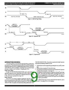
1. Timings referenced as in AC Test Conditions.
2. Industrial temperature range product for 15ns and 25ns speed grades are available as a standard device.
3. Industrial temperature range product for 25ns speed grade only is available as a standard device. All other speed grades are available by special order.
4. Pulse widths less than minimum are not allowed.
5. Values guaranteed by design, not currently tested.
6. Only applies to read data flow-through mode.
4

 IDT [ INTEGRATED DEVICE TECHNOLOGY ]