ICS1531 Data Sheet - Preliminary
Chapter 2 Summary
2.5 Additional PLLs, with Spread Spectrum (Drive Memory and Panel Data Clocks)
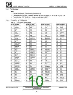
Besides the pixel clock PLL, the ICS1531 has two other independent PLLs for use as needed. Typically,
one of the PLLs is used to drive memory clocks (Regs 26–2B and 2D) and the other PLL is used to drive
panel data clocks (Regs 20–25 and 2D). Both of these additional PLLs are tailored for the required
frequency ranges. Each supports software-controlled spread-spectrum clock dithering to reduce measured
electro-magnetic interference (EMI).
2.6 Dynamic Phase Adjust (Positions Pixel Clock on Sub-Pixel Basis)
Most display controllers provide an HSYNC signal that can be used as a reference signal for the pixel clock.
However, when this HSYNC signal is used as an input, frequently it has significant jitter that impacts data
capture. Furthermore, the analog data stream from the display controller to the ICS1531 has no pixel-rate
reference clock.
So that analog pixel data inputs can be properly sampled and digitized, the ICS1531’s pixel PLL tracks the
input HSYNC signal and the line-to-line jitter. To provide a properly aligned sampling clock (ADCSYNC) to
the ADC blocks, the ICS1531’s Dynamic Phase Adjust (DPA) circuitry can add delays to the pixel clock
position. The delay, which occurs in relation to the edge of ADCSYNC (the recovered HSYNC signal), is
added in sub-pixel time increments.
Regs 04:5-0, 05:1-0 and 06 are used to program the ICS1531 DPA for a value representing incremental
sub-pixel delay units. By choosing the proper value, pixel data to the ICS1531 can be sampled at the
optimum time for proper digitization and the best-looking display. Typically, a system’s microcontroller
presets this value, based on either a table or proprietary algorithms. The end user can change the value
through the system’s on-screen display controls.
Table 2-1 lists the number of possible delay element units that can be used to program to add a delay of up
to one pixel clock period, in increments of either 16, 32, or 64 (Reg 04:5-0 and Reg 5:1-0)
.
Table 2-1. Increments for Delay Element Units
Number of
Pixel Clock Range, MHz
Delay Element Units
16
32
64
55
260
27
130
14
64
Note: To adjust the ICS1531 on a pixel-by-pixel basis, see Section 2.3.6, “Feedback Divider (Controls
Number of Pixel Clocks per HSYNC)”.
2.7 Automatic Power-On Reset Detection (Automatically Resets ICS1531)
The ICS1531 automatically detects power-on resets. As a result, the ICS1531 resets itself if the supply
voltage drops below threshold values. No external connection to a reset signal is required.
2.8 Logic Inputs and Outputs
• Inputs. The ICS1531 uses both of the following inputs:
– Analog inputs
– Digital inputs. The digital inputs are low-voltage TTL (LVTTL) inputs that operate at 3.3 V. These
LVTTL inputs are also 5-V tolerant. (For inputs that are 5-V tolerant, see Section 3.2.3.10, “List of 5-V
Tolerant Pins”.)
• Outputs. The ICS1531 has high-speed LVTTL clock outputs.
ICS1531 Rev N 12/1/99
December, 1999
Copyright © 1999, Integrated Circuit Systems, Inc.
All rights reserved.
7

 ICSI [ INTEGRATED CIRCUIT SOLUTION INC ]