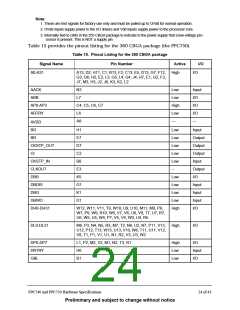
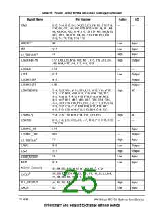
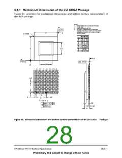
6.1.1 Mechanical Dimensions of the 255 CBGA Package
Figu re 15 provides th e m ech an ical dim en sion s an d bottom su rface n om en clatu re of
th e BGA package.
NOTES:
1.
DIMENSIONING AND TOLERANCING PER ASME
Y14.5M, 1994.
2X
2.
3.
DIMENSIONS IN MILLIMETERS.
TOP SIDE A1 CORNER INDEX IS A METALIZED
FEATURE WITH VARIOUS SHAPES. BOTTOM SIDE A1
CORNER IS DESIGNATED WITH A BALL MISSING
FROM THE ARRAY.
0.2
D
A
A1 CORNER
MILLIMETERS
DIM
A
A1
A2
b
MIN
2.45
0.80
0.90
0.82
MAX
3.00
1.00
1.10
0.93
D
21.00 BSC
D1
e
E
5.00
16.00
1.27 BSC
21.00 BSC
5.00 16.00
E
E1
E1
C
2X
0.2
0.15
C
D1
B
1
2
3
4
5
6
7
8
9
10 11 12 13 14 15 16
T
R
P
N
M
L
e/2
K
J
H
G
F
E
D
C
B
A
e
e/2
255X
b
A2
A1
0.3
C A B
C
0.15
A
Figure 15. Mechanical Dimensions and Bottom Surface Nomenclature of the 255 CBGA Package
PPC740 and PPC750 Hardware Specifications
28 of 43
Preliminary and subject to change without notice

 IBM [ IBM ]