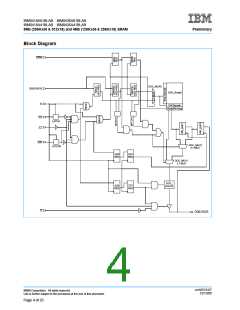
IBM0418A81BLAB IBM0436A81BLAB
IBM0418A41BLAB IBM0436A41BLAB
8Mb (256Kx36 & 512x18) and 4Mb (128Kx36 & 256Kx18) SRAM
Preliminary
DC Electrical Characteristics (TA = 0 to +85°C, VDD = 2.5V -5%, +5%)
Parameter
Symbol
Min.
Max.
Units
A
Notes
1, 3
I
DD3
0.470
0.450
0.435
0.420
0.370
I
DD3F
DD3N
Average Power Supply Operating Current - x36
—
—
I
(I
= 0, V = V or V , ZZ & SS = V )
IN IH IL IL
OUT
I
I
DD4
DD5
I
I
DD3
0.450
0.430
0.415
0.400
0.350
I
I
DD3F
Average Power Supply Operating Current - x18
(I = 0, V = V or V , ZZ & SS = V )
—
—
1, 3
A
DD3N
OUT
IN
IH
IL
IL
I
I
DD4
DD5
Power Supply Standby Current
(SS = V , ZZ = V . All other inputs = V or V , I = 0)
I
1
—
—
-2
-5
150
100
+2
mA
mA
µA
SBSS
IH
IL
IH
IH IH
Power Supply Sleep Current
(ZZ = V , All other inputs = V or V , I = 0)
IL OUT
I
1, 5
SBZZ
IH
IH
Input Leakage Current, any input (except JTAG)
(V = V or V
I
LI
)
DD
IN
SS
Output Leakage Current
(V = V or V , DQ in High-Z)
I
+5
µA
LO
OUT
SS
DD
Output “High” Level Voltage (I = -8mA)
V
V
-.4
V
2, 4
2, 4
V
V
OH
OH
DDQ
DDQ
Output “Low” Level Voltage (I = +8mA)
V
V
V
+.4
SS
OL
OL
SS
JTAG Leakage Current
I
6
-50
+10
µA
LIJTAG
(V = V or V
)
IN
SS
DD
1. I
= Chip Output Current.
OUT
2. Minimum Impedance Output Driver.
3. The numeric suffix indicates part operating at speed as indicated in AC Characteristics on page 11: i.e., I
indicates 3ns cycle
DD3
time.
4. JEDEC Standard JESD8-6 Class 1 Compatible.
5. When ZZ = High, spec is guaranteed at 75°C junction temperature.
6. For JTAG inputs only.
PBGA Thermal Characteristics
Item
Symbol
Rating
1
Units
Thermal Resistance Junction to Case
RΘJC
°C/W
Capacitance (TA = 0 to +85°C, VDD = 2.5V -5%, +5%, f = 1MHz)
Parameter
Symbol
Test Condition
Max
Units
pF
C
V
= 0V
= 0V
Input Capacitance
4
4
IN
IN
C
V
OUT
Data I/O Capacitance (DQ0-DQ35)
pF
OUT
crrh2519.07
12/13/00
©IBM Corporation. All rights reserved.
Use is further subject to the provisions at the end of this document.
Page 8 of 25

 IBM [ IBM ]