HY2213
1 Cell Li Battery Charge Balance IC
10.Description of Operation
10.1.Normal Status
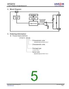
This IC continuing monitor the battery voltage connected between VDD and VSS to control
charge balance operation. When battery voltage is higher than overcharge detection
voltage (VCU), OUT pin output low potential to control P-MOSFET or output high potential to
control N-MOSFET. When battery voltage under overcharge release voltage (VCR), OUT
pin output high potential to control P-MOSFET or output low potential to turnoff N-MOSFET.
10.2.Overcharge Status
When charging battery under normal operation, once cell voltage exceeds over charge
detection voltage (VCU) and this status continues longer than overcharge detection delay
time (TOC), or when cell voltage lower than overcharge release voltage (VCR), HY2213
series will start or turn off the MOSFET (OUT pin) that used for charging potential control,
this status is called “Overcharge Status”, also “Charge Balance Control”.
There are two options of balancing control of MOSFET after overcharge status:
(1) HY2213-xxxA series adopts N-MOSFET to implement charge balancing control
(a) Cell voltage exceeds overcharge detection voltage (VCU) during charge
process and lasts longer than overcharge detection delay time (TOC), potential
of OUT pin will generate LH change to turn on N-MOSFET.
.
(b) Cell voltage lowers than overcharge release voltage (VCR) during charge
process, OUT pin will generate HL change to turn off N-MOSFET.
(2) HY2213-xxxB series adopts P-MOSFET to implement charge balancing control
(a) Cell voltage exceeds overcharge detection voltage (VCU) during charge
process and lasts longer than overcharge detection delay time (TOC), potential
of OUT pin will generate HL change to turn on P-MOSFET.
(b) Cell voltage lowers than overcharge release voltage (VCR) during charge
process, OUT pin will generate LH change to turn off P-MOSFET.
10.3.Standby Status
When discharging battery under normal operation, cell voltage drops under than standby
detection voltage (VSB), it will reduce IC current consumption to the same level at standby
mode, and this is called “Standby Mode”.
© 2012-2015 HYCON Technology Corp
www.hycontek.com
DS-HY2213-V05_EN
Page 9

 HYCON [ HYCON Technology Corporation ]