Fast PFET Buck Controller
LM51031
the PFET off. As VCC and VC continue to rise, the
oscillator capacitor (COSC) and Soft start/Fault
Timing capacitor(CS) charges via internal current
sources. COSC gets charged by the current source
IC and CS gets charged by the IT source
combination described by:
Lossless Short Circuit Protection
The LM51031 has “lossless” short circuit protection
since there is no current sense resistor reguired.
When the voltage at the CS pin (the fault timing
capacitor voltage) reaches 2.5V during startup, the
fault timing circuitry is enabled. During normal operation
the CS voltage is 2.6V. During a short circuit or a
transient condition, the output voltage moves lower and
the voltage at VFB drops. If VFB drops below 1.15V,
the output of the fault comparator goes high and the
LM51031 goes into a fast discharge mode. The fault
timing capacitor, CS, discharges to 2.4V. If the VFB
voltage is still below 1.15V when the CS pin reaches
2.4V, a valid fault condition has been detected. The
slow discharge comparator output goes high and
enables gate G5 which sets the slow discharge flip
flop. The Vgate flip flop resets and the output switch is
turned off. The fault timing capacitor is slowly
The internal Holdoff Comparator ensures that the
external PFET is off until VCS > 0.7V, preventing the
GATE flip-flop (F2) from being set. This allows the
oscillator to reach its operating frequency before
enabling the drive output. Soft start is obtained by
clamping the VFB comparator’s (A6) reference input
to approximately 1/2 of the voltage at the CS pin
during startup, permitting the control loop and the
output voltage to slowly increase. Once the CS pin
charges above the Holdoff Comparator trip point of
0.7V, the low feedback to the VFB Comparator sets
the GATE flip-flop during COSC ’s charge cycle.
Once the GATE flip-flop is set, VGATE goes low and
turns on the PFET. When VCS exceeds 2.4V, the CS
charge sense comparator (A4) sets the VFB
comparator reference to 1.25V completing the startup
cycle.
discharged to 1.5V. The LM51031 then enters a normal
startup routine. If the fault is still present when the
fault timing capacitor voltage reaches 2.5V, the fast and
slow discharge cycles repeat as shown in figure 2.
If the VFB voltage is above 1.15V when CS reaches
2.4V a fault condition is not detected, normal operation
resumes and CS charges back to 2.6V. This reduces the
chance of erroneously detecting a load transient as a
fault condition.
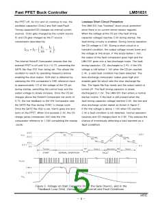
Figure 3. Voltage on Start Capacitor (VGS), the Gate (VGATE), and in the
Feedback Loop (VFB), During Startup, Normal and Fault Conditions
HTC
− 5 −

 HTC [ HTC KOREA TAEJIN TECHNOLOGY CO. ]