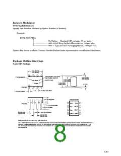
8-pin DIP Gull Wing Surface Mount Option 300
PIN LOCATION (FOR REFERENCE ONLY)
9.65 ± 0.25
(0.380 ± 0.010)
1.02 (0.040)
1.19 (0.047)
7
6
5
8
1
4.83
(0.190)
TYP.
6.350 ± 0.25
(0.250 ± 0.010)
9.65 ± 0.25
(0.380 ± 0.010)
2
3
4
MOLDED
0.380 (0.015)
0.635 (0.025)
1.19 (0.047)
1.78 (0.070)
9.65 ± 0.25
(0.380 ± 0.010)
1.780
(0.070)
MAX.
1.19
(0.047)
MAX.
7.62 ± 0.25
(0.300 ± 0.010)
0.255 (0.075)
0.010 (0.003)
4.19
MAX.
(0.165)
0.635 ± 0.25
(0.025 ± 0.010)
1.080 ± 0.320
(0.043 ± 0.013)
0.51 ± 0.130
(0.020 ± 0.005)
12° NOM.
2.540
(0.100)
BSC
DIMENSIONS IN MILLIMETERS (INCHES).
TOLERANCES (UNLESS OTHERWISE SPECIFIED): xx.xx = 0.01
xx.xxx = 0.005
LEAD COPLANARITY
MAXIMUM: 0.102 (0.004)
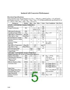
Package Characteristics
Unless otherwise noted, all specifications are at T = +25°C.
A
Parameter
Input-Output Momentary
Withstand Voltage
Symbol Min. Typ. Max. Units
Test Conditions
RH ≤ 50%, t = 1 min.
Note
14,15
V
3750
V
rms
ISO
(See note ** below)
Resistance (Input - Output)
12
13
R
10
10
Ω
V
I-O
= 500 Vdc
15
I-O
11
10
T = 100°C
A
Capacitance
(Input - Output)
Input IC Junction-to-Case
Thermal Resistance
C
0.7
pF
f = 1 MHz
I-O
jci
θ
96
°C/W Thermocouple located at
center underside of
package
Output IC Junction-to-Case
Thermal Resistance
θ
114
°C/W
jco
** The Input-Output Momentary Withstand Voltage is a dielectric voltage rating that should not be interpreted as an input-output
continuous voltage rating. For the continuous voltage rating refer to your equipment level safety specification or HP Application Note
1074, Optocoupler Input-Output Endurance Voltage.
1-268

 HP [ HEWLETT-PACKARD ]