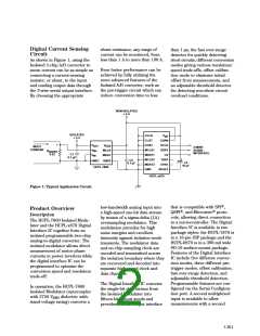
isolated modulator without
additional hardware. Because the
two inputs are multiplexed, only
one conversion at a time can be
made and not all features are
available for the second channel.
The available features for both
channels are shown in the table
at right.
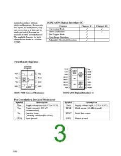
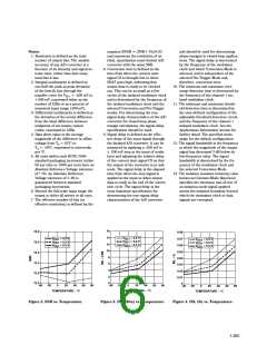
HCPL-x870 Digital Interface IC
Feature
Conversion Mode
Channel #1
Channel #2
✓
✓
✓
✓
✓
✓
✓
Offset Calibration
Pre-Trigger Mode
Over-Range Detection
Adjustable Threshold Detection
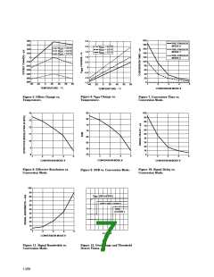
Functional Diagrams
ISOLATION
BOUNDARY
CCLK
CLAT
V
1
2
3
4
5
6
7
8
16
15
DD
CONFIG.
INTER-
FACE
CHAN
CON-
VERSION
INTER-
FACE
V
V
DD1
1
2
3
4
8
7
6
5
DD2
CDAT
14 SCLK
13 SDAT
MCLK1
MDAT1
MCLK2
MDAT2
GND
V
MCLK
MDAT
GND2
IN+
SIGMA-
DELTA
MOD./
CH1
CH2
CS
DECODE
12
11
V
ENCODE
IN–
THRES-
HOLD
DETECT
&
THR1
10 OVR1
RESET
GND1
SHIELD
RESET
9
HCPL-7860 Isolated Modulator
HCPL-x870 Digital Interface IC
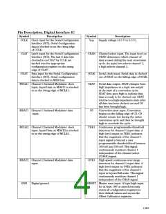
Pin Description, Isolated Modulator
Symbol
Description
Symbol
Description
V
Supply voltage input (4.5 V to 5.5 V)
Positive input (± 200 mV
recommended)
Negative input
(normally connected to GND1)
Input ground
V
Supply voltage input (4.5 V to 5.5 V)
Clock output (10 MHz typical)
DD1
DD2
V
IN+
MCLK
MDAT
GND2
V
Serial data output
Output ground
IN–
GND1
1-262

 HP [ HEWLETT-PACKARD ]