HI-6110 (REMOTE TERMINAL MODE)
REMOTE TERMINALOPERATION
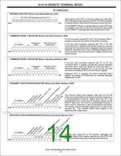
The Receive Data FIFO is cleared at Master Reset, or by
performing a series of FIFO read operations until FFEMPTY goes
high. The Receive Data FIFO will not accept new receive data
when full.
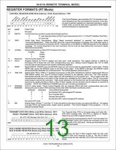
The HI-6110 remote terminal (RT) address is set by wiring the
RTA4:RTA0 input pins to the desired address. RTA0 is the least
significant address input. The RTAP input must be set/reset to
reflect odd parity for the RA4:0 address inputs. Upon Master
Reset, the HI-6110 reads the RT address inputs and checks for
correct parity. If a parity error is detected, the PARERR bit is set in
the Error Register and the HI-6110 RT will not respond to MIL-
STD-1553 Command Words. The host controller must correct the
RT address-parity mismatch, then reassert Master Reset to
enable bus operations.
When the Control Register is written to change the active bus, the
HI-6110 automatically resets any message in process on the
former bus and begins a new message sequence on the new bus.
To comply with RT response time limits, it is typically necessary to
write the Control Register within 2 uS of the rising edge of the
RCV flag on the alternate bus. Note that when the active bus is
switched, the RT message sequencer retrieves and responds to
the last valid command word received on the previously inactive
bus. This applies regardless of when the command word was
received. For this reason, bus switching should only occur in
response to a current RCV or RCVCMD signal or otherwise be
followed by a master reset.
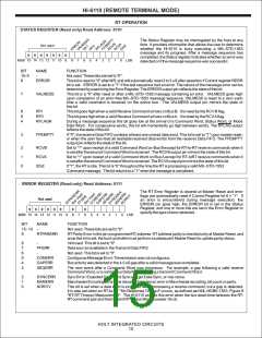
When configured as
a Remote Terminal, the HI-6110
continuously monitors both MIL-STD-1553 buses. Each received
Command Word is checked for validity. The RCVA and RCVB
outputs are asserted only when a received command is valid.
Valid is defined as having an RT address matching the pin-
programmed RT address or the command is a broadcast
command. If a valid command is received on Bus A, the RCVA
signal goes high to notify the host. Similarly, when a valid
command arrives on Bus B, the RCVB signal goes high.
The HI-6110 readily handles superseding commands. For
superseding commands on the same bus as described in 5.2.1.4
of the RT Validation test, the 6110 will generate a new RCV flag
upon receiving a valid command after a 4 uS gap. The message
sequencer is automatically reset and the new sequence initiated.
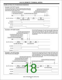
The received command may be read from the appropriate
Command Word register, or the Message register may be read to
quickly determine the type of response needed. The RT protocol
sequencer will initiate a response in accordance with the
requirements of MIL-STD-1553. If the message type requires a
Status Word response and the bus TR bit is set in the Control
Register, the HI-6110 RT will automatically transmit its Status
Word approxinmately 7 to 9 5uS after RCVA or RCVB goes high.
The Status Word register can be modified up to 1.3 uS past mid-
sync, occurring when the Status Word is transmitted.
RT validation section 5.2.1.8 “Bus Switching” tests a condition
otherwise prohibited by the 1553 standard: overlapping valid
commands on the two buses. To meet the requirements of this
test, certain steps are required: (a) When switching buses for the
superseding command, reset Control Register TRA and TRB bits
for 200 nS minimum before setting the TRx bit for the newly active
bus. This resets transmission for an in-process command
response. To simplify the software, the example software does
this for all bus switching. (b) The RT should always respond to the
command occurring last. Apotential problem occurs when an RT-
RT receive command is interrupted by a valid command on the
other bus.Although CW1 is valid for the remote terminal, RCV for
all RT-RT commands occurs after CW1 and CW2 are both
received. When a valid command that overlaps CW1 occurs on
the other bus, its RCV will go high before the RT-RT RCV. The
overlapping command occurs later, although its RCV precedes
the RT-RT RCV. The RT-RT RCV must be ignored. To correctly
respond to the overlapping command, the software must utilize
the RCVCMDA and RCVCMDB signals as described below.
Please refer to the software example in the reference design for a
working implementation.
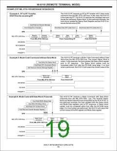
If transmit data words are part of the command response, the
automatic response delay provides time for the host to load the
Transmit Data FIFO. The first data word must be written to the
FIFO not later than 20 uS after Status Word mid-sync. All data
words must be written before mid-sync occurring within its
transmission window. All data words may be written in rapid
succession once RCVAor RCVB goes high.
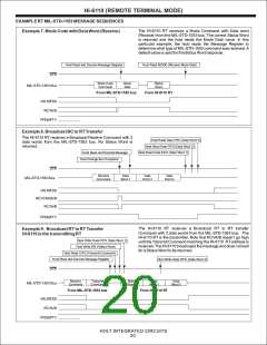
Upon error-free completion of the message, VALMESS goes
high. (One exception: broadcast mode code commands without
mode data word do not generate VALMESS.) If an error is
detected, VALMESS remains low and the ERROR signal goes
high. The ERROR register can be read to determine error type.
The RCVCMDAoutput goes high when a valid non-mode receive
command is decoded on Bus A. The RCVCMDB signal performs
the same function for Bus B. Successful compliance with RT
validation 5.2.1.8 “Bus Switching” requires host interaction when
RCVCMD is asserted for the inactive bus. When this occurs, the
host should immediately make that bus active. If an ordinary
receive command is coming from the Bus Controller, RCV for the
newly-active bus will go high about 4 uS after RCVCMD. If an RT-
RT receive command, RCV follows RCVCMD by 20 uS. In either
case once RCV is asserted, the RT can begin polling FFEMPTY
to acquire received data words as they arrive.
In applications requiring illegal command detection, the HI-6110
readily handles command “illegalization”. Upon detecting an
illegal command, the host microcontroller takes steps to (a) send
the Remote Terminal Status Word with the Message Error (ME)
bit set (non-broadcast commands only), and (b) suppress
transmission of any data words associated with the normal
response to the command. For part (a), the Status Word register
is modified by setting the ME bit. This is done first to make sure the
change is effective before Status Word transmission begins. For
part (b), bit 13 in the Control Register is set to suppress data word
transmission.
NOTE: Once bit 13 is set in the Control register, the affected
message will NOT conclude with VALMESS or ERROR
assertion. Control Register bit 13 should be written to a zero
before the next message is processed. The host might perform
the Control Register write as part of the RCV flag service routine
in order to restore normal operation for legal commands.
HOLT INTEGRATED CIRCUITS
17

 HOLTIC [ HOLT INTEGRATED CIRCUITS ]