HI-6110 (REMOTE TERMINAL MODE)
RT OPERATION
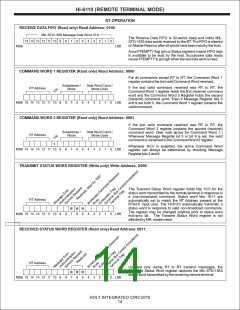
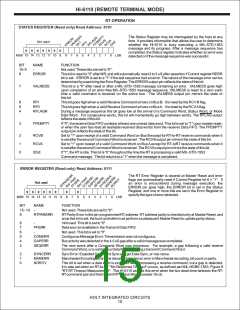
STATUS REGISTER (Read only) Read Address: 0101
The Status Register may be interrogated by the host at any
time. It provides information that allows the user to determine
whether the HI-6110 is busy executing a MIL-STD-1553
message and its progress. After a message sequence has
completed, the Status register indicates whether an error was
detected or if the message sequence was successful.
A
Not used
ALMESS
ERROVR RF1 RF0 RFLAFGFNEMRPCTVYBRCV IDLE
0
0
0
0
0
0
0
MSB 15 14 13 12 11 10
9
8
7
6
5
4
3
2
1
0
LSB
BIT
15- 9
8
NAME
-
FUNCTION
Not used. These bits are set to "0".
ERROR
This bit is reset to "0" after MR, and will automatically reset 2 to 3 uS after assertion if Control register RERR
bit is set. ERROR is set to a "1" if the last sequence had an error. The nature of the message error can be
determined by examining the Error Register. The ERROR output pin reflects the state of this bit.
7
VALMESS
This bit is a "0" after reset or after a MIL-STD-1553 message containing an error. VALMESS goes high
upon completion of an error-free MIL-STD-1553 message sequence. VALMESS is reset to a zero each
time a valid command is received on the active bus. The VALMESS output pin mirrors the state of
this bit.
6
5
4
RF1
This bit goes high when a valid Receive Command arrives on Bus B. It is reset by the RCV B flag.
This bit goes high when a valid Receive Command arrives on BusA. It is reset by the RCVAflag.
RF0
RFLAGN
During a message sequence this bit goes low at the arrival of a Command Word, Status Word, or Mode
Data Word. For consecutive words, this bit will momentarily go high between words. The RFLAG output
reflects the state of this bit.
3
FFEMPTY
If "0", the receive Data FIFO contains at least one unread data word. This bit is set to "1" upon master reset,
or when the user has read all available received data words from the receiver Data FIFO. The FFEMPTY
output pin reflects the state of this bit.
2
1
0
RCVB
RCVA
IDLE
Set to "1" upon receipt of a valid Command Word on Bus B except for RT-to-RT receive commands when it
is set after the second Command Word is received. The RCVB output pin mirrors the state of this bit.
Set to "1" upon receipt of a valid Command Word on Bus A except for RT-toRT receive commands when it
is set after the second Command Word is received. The RCVAoutput pin mirrors the state of this bit.
If "1", the RTis idle. This bit is “0” throughout the time the RTis processing a valid MIL-STD-1553
Command message. The bit returns to a "1" when the message is completed.
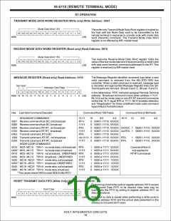
ERROR REGISTER (Read only) Read Address: 0111
The RT Error Register is cleared at Master Reset and error
flags are automatically reset if Control Register bit 6 = “1”. If
an error is encountered during message execution, the
ERROR pin goes high, the ERROR bit is set in the Status
Register, and one or more bits are set in the Error Register to
specify the type of error detected.
Not used
0
0
0
0
0
0
0
0
MSB 15 14 13 12 11 10
9
8
7
6
5
4
3
2
1
0
LSB
BIT
15 - 10
9
NAME
FUNCTION
Not used. These bits are set to "0".
-
RTPARERR
RT Parity Error in the pin-programmed RT address. RT address parity is checked only at Master Reset, and
once this bit is set, the host controller must perform a subsequent Master Reset to update parity status.
8
7
6
5
4
3
-
Not used. This bit is set to "0".
FFERR
-
Data was not available in theTransmit Data FIFO.
Not used. This bit is set to "0".
CONERR
GAPERR
SEQERR
Contiguous Message Error:Transmission was not contiguous.
Bus activity was detected in the 4.0 uS gap after a valid message was completed.
The next event after a Command Word was erroneous. For example, a gap following a valid receive
Command Word, or a contiguous Data Word following a transmit Command Word.
2
1
0
SYNCERR
MANERR
NORCV
Sync Error: Expected Command Sync and got Data Sync, or vice versa.
Manchester Encoding Error:The decoder detected an error in Manchester encoding, bit count or parity.
This bit is set when a data word is expected while processing a receive command, but a gap is detected.
It is also set when an RT-to-RT "No Response Timeout" occurs, as defined per MIL-HDBK-1553, Figure 8
"RT-RT Timeout Measurement". The HI-6110 asserts this error when the bus dead-time between the RT-
RTcommand pair and the transmit RTStatus Word exceeds 15 uS.
HOLT INTEGRATED CIRCUITS
15

 HOLTIC [ HOLT INTEGRATED CIRCUITS ]