HI-1575
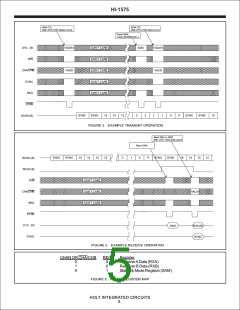
The host reads the received word from the HI-1575 RXAor
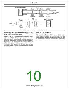
MIL-STD-1553 BUS CONNECTION
RXB register. The data word is read by pulsing STRB low,
while R/W is high and REG is low. Figure 4 shows an
example receive operation. The SYNC output indicates
whether the word had a Command Sync (SYNC=1) or
Data Sync (SYNC=0). SAM register bits 8 and 12
(RSYNCA and RSYNCB) retain the Sync values for the
last word received on each bus.
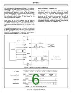
The HI-1575 includes on-chip MIL-STD-1553 analog
transceivers which are designed to drive the primary
winding of a 1:2.5 turns-ratio MIL-STD-1553 isolation
transformer. Figure 6 shows how the HI-1575 may be
connected to the MIL-STD-1553 data bus as either a
direct coupled stub (Bus A example), or a transformer
coupled stub (Bus B example). Holt Integrated Circuits
offers a wide range of single-core and dual-core coupling
transformers suitable for use with the HI-1575.
SAM bits 2 or 3 (RENA, RENB) can be used to
independently enable or disable each receiver. Writing a
'1' to RENA enables receiver A. A '0' disables the receiver.
RENB performs the same function for the MIL-STD-1553
bus B.
Note that because each receiver is internally connected to
its transmitter, when a MIL-STD-1553 word is transmitted
by the HI-1575 it will also be received on the same
channel. This feature allows the terminal to self-monitor
data transmitted to the MIL-STD-1553 data bus.
3.3 V
VDD
CLK
12.0 MHz
55 Ohms
BUSA
BUSA
STRB
R/W
MIL-STD-1553
BUS A
(Direct Coupled)
55 Ohms
CHA/CHB
REG
1:2.5
Host CPU
D15:D0
SYNC
HI-1575
RCVA
RCVB
ERROR
MR
52.5 Ohms
MIL-STD-1553
BUS B
(Transformer Coupled)
52.5 Ohms
BUSB
BUSB
1:2.5
1:1.4
GND
FIGURE 6. MIL-STD-1553 BUS CONNECTION
1
2
3
4
5
6
7
8
9
10 11 12 13 14 15 16 17 18 19 20
Bit Period
SYNC
TERMINAL ADDRESS R/T
SUBADDRESS
/ MODE
DATA WORD
COUNT
P
P
P
Command Word
Data Word
SYNC
SYNC
DATA WORD
SYNC
SYNC
TERMINAL ADDRESS ME
CODE FOR FAILURE MODES
TF
Status Word
SYNC
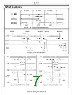
FIGURE 7. MIL-STD-1553 WORD FORMATS
HOLT INTEGRATED CIRCUITS
6

 HOLTIC [ HOLT INTEGRATED CIRCUITS ]