HI-1575
4
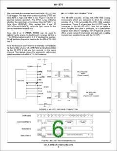
VDD
30
CLK
STRB
R/W
10
9
2
3
11
BUSA
BUSA
MR
Encoder
5
6
BUSB
BUSB
31
CHA/CHB
13-20,
22-29
DATABUS
SYNC
12
1
Decoder A
RCVA
Decoder B
7
RCVB
6
10
32
ERROR
21
GND
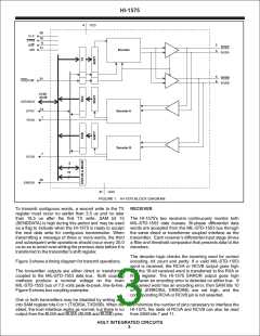
FIGURE 1. HI-1575 BLOCK DIAGRAM
To transmit contiguous words, a second write to the TX RECEIVER
register must occur no earlier than 3.5 us and no later
than 18.5 us after the first TX write. SAM bit 15 The HI-1575's two receivers continuously monitor both
(SENDDATA) is high during this period and may be used MIL-STD-1553 data busses. Bi-phase differential data
as a flag to indicate when the HI-1575 is ready to accept words are accepted from the MIL-STD-1553 bus through
the next data write for contiguous transmission. When the same direct or transformer coupled interface as the
transmitting a message of three or more words, the third transmitter. Each receiver’s differential input stage drives
and subsequent write operations should occur every 20.0 a filter and threshold comparator that presents data to the
us so as to avoid over-writing the previous data before it is decoders.
transferred to the transmitter's shift register.
The decoder logic checks the incoming word for correct
encoding, bit count and parity. If a valid MIL-STD-1553
word is received, the RCVA or RCVB output goes high
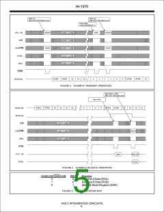
Figure 3 shows a timing diagram for transmit operations.
The transmitter outputs are either direct or transformer and the 16-bit received word is transferred to the RXA or
coupled to the MIL-STD-1553 data bus. Both coupling RXB register. The HI-1575 ERROR output goes high
methods produce a nominal voltage on the main whenever an encoding error is detected on either bus. If
MIL-STD-1553 bus of 7.5 volts peak-to-peak, line-to-line. a received word has an encoding error, then SAM bits 10
Figure 6 shows bus coupling examples.
or 14 (ERRORA, ERRORB) are set high, and the
corresponding RCVA or RCVB pin is not asserted.
One or both transmitters may be disabled by writing a '1'
into SAM register bits 0 or 1 (TXDISA, TXDISB). When dis- To minimize the number of pins necessary to interface the
abled, the host interface works as normal, but there is no HI-1575, the state of RCVA and RCVB can also be read
output from the BUSA and BUSA (BUSB and BUSB) pins.
from SAM bits 7 and 11.
HOLT INTEGRATED CIRCUITS
3

 HOLTIC [ HOLT INTEGRATED CIRCUITS ]