HT46R01B/02B/01N/02N
HT48R01B/02B/01N/02N
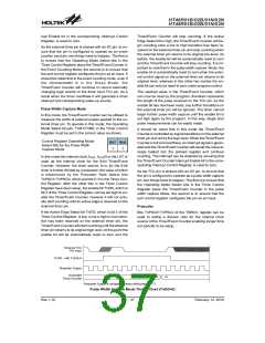
When the Timer/Event Counter overflows, its corre-
sponding interrupt request flag in the interrupt control
register will be set. If the Timer/Event Counter interrupt
is enabled this will in turn generate an interrupt signal.
However irrespective of whether the interrupts are en-
abled or not, a Timer/Event Counter overflow will also
generate a wake-up signal if the device is in a
Power-down condition. This situation may occur if the
Timer/Event Counter is in the Event Counting Mode and
if the external signal continues to change state. In such
a case, the Timer/Event Counter will continue to count
these external events and if an overflow occurs the de-
vice will be woken up from its Power-down condition. To
prevent such a wake-up from occurring, the timer inter-
rupt request flag should first be set high before issuing
the ²HALT² instruction to enter the Sleep Mode.
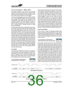
Timer Program Example
The program shows how the Timer/Event Counter regis-
ters are setup along with how the interrupts are enabled
and managed. Note how the Timer/Event Counter is
turned on, by setting bit 4 of the Timer Control Register.
The Timer/Event Counter can be turned off in a similar
way by clearing the same bit. This example program sets
the Timer/Event Counters to be in the timer mode, which
uses the internal system clock as their clock source.
·
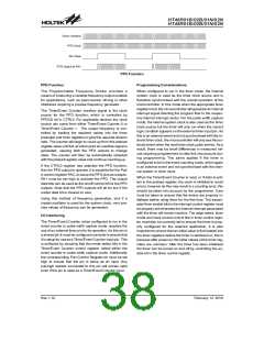
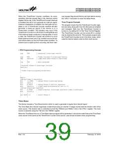
PFD Programming Example
org
04h
; external interrupt vector
org
Jmp
:
08h
tmr0int
:
; Timer Counter 0 interrupt vector
; jump here when Timer 0 overflows
org
:
20h
:
; main program
;internal Timer 0 interrupt routine
tmr0int:
:
; Timer 0 main program placed here
:
:
begin:
;setup Timer 0 registers
mov
mov
mov
mov
a,09bh
tmr0,a
a,081h
tmr0c,a
; setup Timer 0 preload value
; setup Timer 0 control register
; timer mode and prescaler set to /2
;setup interrupt register
mov
mov
:
a,00dh
intc0,a
:
; enable master interrupt and both timer interrupts
; start Timer 0
set tmr0c.4
:
:
Time Base
The device includes a Time Base function which is used to generate a regular time interval signal.
The Time Base time interval magnitude is determined using an internal 13 stage counter sets the division ratio of the
clock source. This division ratio is controlled by both the TBSEL0 and TBSEL1 bits in the CTRL1 register. The clock
source is selected using the T0S bit in the TMR0C register.
When the Time Base time out, a Time Base interrupt signal will be generated. It should be noted that as the Time Base
clock source is the same as the Timer/Event Counter clock source, care should be taken when programming.
Rev.1.10
39
February 12, 2010

 HOLTEK [ HOLTEK SEMICONDUCTOR INC ]