HT46R64/HT46C64
During the execution of an interrupt subroutine, other
maskable interrupt acknowledgments are all held until
the ²RETI² instruction is executed or the EMI bit and the
related interrupt control bit are set both to 1 (if the stack
is not full). To return from the interrupt subroutine, ²RET²
or ²RETI² may be invoked. RETI sets the EMI bit and en-
ables an interrupt service, but RET does not.
It is recommended that a program should not use the
²CALL subroutine² within the interrupt subroutine. It¢s be-
cause interrupts often occur in an unpredictable manner
or require to be serviced immediately in some applica-
tions. During that period, if only one stack is left, and en-
abling the interrupt is not well controlled, operation of the
²call² in the interrupt subroutine may damage the origi-
nal control sequence.
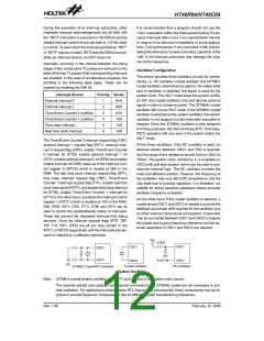
Interrupts occurring in the interval between the rising
edges of two consecutive T2 pulses are serviced on the
latter of the two T2 pulses if the corresponding interrupts
are enabled. In the case of simultaneous requests, the
priorities in the following table apply. These can be
masked by resetting the EMI bit.
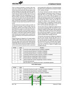
Oscillator Configuration
The device provides three oscillator circuits for system
clocks, i.e., RC oscillator, crystal oscillator and 32768Hz
crystal oscillator, determined by options. No matter what
type of oscillator is selected, the signal is used for the
system clock. The HALT mode stops the system oscilla-
tor (RC and crystal oscillator only) and ignores external
signal in order to conserve power. The 32768Hz crystal
oscillator still runs at HALT mode. If the 32768Hz crystal
oscillator is selected as the system oscillator, the system
oscillator is not stopped; but the instruction execution is
stopped. Since the 32768Hz oscillator is also designed
for timing purposes, the internal timing (RTC, time base,
WDT) operation still runs even if the system enters the
HALT mode.
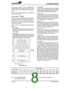
Interrupt Source
External interrupt 0
Priority Vector
1
2
3
4
5
6
04H
08H
0CH
10H
14H
18H
External interrupt 1
Timer/Event Counter 0 overflow
Timer/Event Counter 1 overflow
Time base interrupt
Real time clock interrupt
The Timer/Event Counter 0 interrupt request flag (T0F),
external interrupt 1 request flag (EIF1), external inter-
rupt 0 request flag (EIF0), enable Timer/Event Counter
0 interrupt bit (ET0I), enable external interrupt 1 bit
(EEI1), enable external interrupt 0 bit (EEI0) and enable
master interrupt bit (EMI) make up of the Interrupt Con-
trol register 0 (INTC0) which is located at 0BH in the
RAM. The real time clock interrupt request flag (RTF),
time base interrupt request flag (TBF), Timer/Event
Counter 1 interrupt request flag (T1F), enable real time
clock interrupt bit (ERTI), and enable time base interrupt
bit (ETBI), enable Timer/Event Counter 1 interrupt bit
(ET1I) on the other hand, constitute the Interrupt Control
register 1 (INTC1) which is located at 1EH in the RAM.
EMI, EEI0, EEI1, ET0I, ET1I, ETBI and ERTI are all
used to control the enable/disable status of interrupts.
These bits prevent the requested interrupt from being
serviced. Once the interrupt request flags (RTF, TBF,
T0F, T1F, EIF1, EIF0) are all set, they remain in the
INTC1 or INTC0 respectively until the interrupts are ser-
viced or cleared by a software instruction.
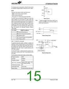
Of the three oscillators, if the RC oscillator is used, an
external resistor between OSC1 and VSS is required,
and the range of the resistance should be from 30kW to
750kW. The system clock, divided by 4, is available on
OSC2 with pull-high resistor, which can be used to syn-
chronize external logic. The RC oscillator provides the
most cost effective solution. However, the frequency of
the oscillation may vary with VDD, temperature, and the
chip itself due to process variations. It is therefore, not
suitable for timing sensitive operations where accurate
oscillator frequency is desired.
On the other hand, if the crystal oscillator is selected, a
crystal across OSC1 and OSC2 is needed to provide the
feedback and phase shift required for the oscillator, and
no other external components are required. A resonator
may be connected between OSC1 and OSC2 to replace
the crystal and to get a frequency reference, but two ex-
ternal capacitors in OSC1 and OSC2 are required.
V
D
D
4
7
0
p
F
O
S
C
1
O
S
C
1
O
S
C
3
O
S
C
4
S
Y
S
O
S
C
2
O
S
C
2
C
r
y
s
t
a
l
O
s
c
i
l
l
a
t
o
r
R
C
O
s
c
i
l
l
a
t
o
r
3
2
7
6
8
H
z
C
r
y
s
t
a
l
/
R
T
C
O
s
c
i
l
l
a
t
o
r
System Oscillator
Note: 32768Hz crystal enable condition: For WDT clock source or for system clock source.
The external resistor and capacitor components connected to the 32768Hz crystal are not necessary to pro-
vide oscillation. For applications where precise RTC frequencies are essential, these components may be re-
quired to provide frequency compensation due to different crystal manufacturing tolerances.
Rev. 1.80
12
February 14, 2006
图片预览")
 HOLTEK [ HOLTEK SEMICONDUCTOR INC ]