HT45R37
Oscillator
Various oscillator options offer the user a wide range of
functions according to their various application require-
ments. Five types of system clocks can be selected
while various clock source options for the Watchdog
Timer are provided for maximum flexibility. All oscillator
options are selected through the configuration options.
More information regarding oscillator applications is lo-
cated on the Holtek website.
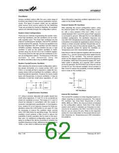
External System RC Oscillator
After selecting the correct configuration option, using
the external system RC oscillator requires that a resis-
tor, with a value between 47kW and 1.5MW, is con-
nected between OSC1 and VDD, and a 470pF capacitor
is connected to ground. Although this is a cost effective
oscillator configuration, the oscillation frequency can
vary with VDD, temperature and process variations and
is therefore not suitable for applications where timing is
critical or where accurate oscillator frequencies are re-
quired. For the value of the external resistor ROSC refer
to the Appendix section for typical RC Oscillator vs.
Temperature and VDD characteristics graphics.
System Clock Configurations
There are six methods of generating the system clock,
three high oscillators, two low oscillators and an exter-
nally supplied clock. The three high oscillators are the
external crystal/ceramic oscillator, internal RC oscillator
and the external RC network. The two low oscillators are
the fully integrated 32K_INT oscillator and the external
32768Hz oscillator. Selecting whether the low or high
oscillator is used as the system oscillator is imple-
mented using the HLCLK bit in the CLKMOD register.
The source clock for the high and low oscillators is cho-
sen via configuration options. The frequency of the slow
oscillator is also determined using the
SLOWC0~SLOWC2 bits in the CLKMOD register.
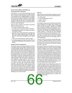
Note that an internal capacitor together with the external
resistor, ROSC, are the components which determine the
frequency of the oscillator. The external capacitor
shown on the diagram does not influence the frequency
of oscillation. Note that if this external system RC oscil-
lation option is selected, as it requires OSC1 external
pin for its operation, the PC2/OSC2 pin is free for use as
normal I/O pin.The internal oscillator circuit contains a
filter circuit to reduce the possibility of erratic operation
due to noise on the oscillator pins.
System Crystal/Ceramic Oscillator
After selecting the external crystal configuration option,
the simple connection of a crystal across OSC1 and
OSC2, is normally all that is required to create the nec-
essary phase shift and feedback for oscillation, without
requiring external capacitors. However, for some crystal
types and frequencies, to ensure oscillation, it may be
necessary to add two small value capacitors, C1 and
V
D
D
R
O
S
C
O
S
C
1
C
1
O
S
C
1
4
7
0
p
F
R
1
P
C
2
O
S
C
2
C
2
RC Oscillator
Crystal/Ceramic Oscillator
Internal RC Oscillator
C2. Using a ceramic resonator will usually require two
small value capacitors, C1 and C2, to be connected as
shown for oscillation to occur. The values of C1 and C2
should be selected in consultation with the crystal or
resonator manufacturer¢s specification. In most applica-
tions, resistor R1 is not required, however for those ap-
plications where the LVR function is not used, R1 may
be necessary to ensure the oscillator stops running
when VDD falls below its operating range. The internal
oscillator circuit contains a filter circuit to reduce the
possibility of erratic operation due to noise on the oscil-
lator pins. An additional configuration option must be
setup to configure the device according to whether the
oscillator frequency is high, defined as equal to or above
1MHz, or low, which is defined as below 1 MHz.
The internal RC oscillator is a fully integrated system os-
cillator requiring no external components. The internal
RC oscillator has three fixed frequencies of either
4MHz, 8MHz or 12MHz, the choice of which is indicated
by the configuration options. Note that if this internal
system clock option is selected, as it requires no exter-
nal pins for its operation, the OSC1 and OSC2 pins are
free for use as normal I/O pins. Refer to the Appendix
section for more information on the actual internal oscil-
lator frequency vs. Temperature and VDD characteris-
tics graphics.
Rev. 1.20
62
February 25, 2011
图片预览")
 HOLTEK [ HOLTEK SEMICONDUCTOR INC ]