HT45R37
·
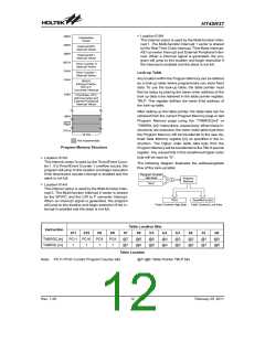
Location 018H
0
0
0
0
0
0
0
4
8
H
H
H
I
n
i
t
i
a
l
i
s
a
t
i
o
n
This internal vector is used by the Multi-function Inter-
rupt 1. The Multi-function Interrupt 1 vector is shared
by the Real Time Clock interrupt, Time Base interrupt,
A/D converter interrupt and External Peripheral inter-
rupt. When a interrupt signal is generated, the pro-
gram will jump to this location and begin execution if
the interrupt is enabled and the stack is not full.
V
e
c
t
o
r
E
x
t
e
r
n
a
l
I
N
T
0
I
n
t
e
r
r
u
p
t
V
e
c
t
o
E
x
t
e
r
n
a
l
I
N
T
1
I
I
I
n
n
n
t
t
t
e
e
e
r
r
r
r
r
r
u
u
u
p
p
p
t
t
t
V
V
V
e
e
e
c
c
c
t
t
t
o
o
o
0
0
C
H
T
i
m
e
r
C
o
u
n
t
e
r
0
0
1
0
H
T
i
m
e
r
C
o
u
n
t
e
r
1
Look-up Table
Any location within the Program Memory can be defined
as a look-up table where programmers can store fixed
data. To use the look-up table, the table pointer must
first be setup by placing the lower order address of the
look up data to be retrieved in the table pointer register,
TBLP. This register defines the lower 8-bit address of
the look-up table.
0
1
4
H
2
S
P
C
I
/
I
I
n
t
e
r
r
u
p
t
V
e
c
t
o
R
/
C
t
o
F
C
o
n
v
e
r
t
e
r
I
n
t
e
r
0
1
8
H
T
i
m
e
B
a
s
e
,
R
T
C
A
/
D
C
o
n
v
e
r
t
e
r
a
E
x
t
e
r
n
a
l
P
e
r
i
p
h
I
n
t
e
r
r
u
p
t
V
e
c
t
o
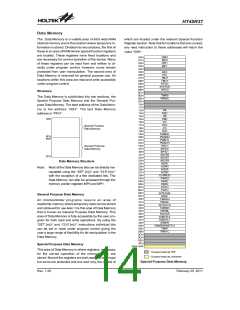
After setting up the table pointer, the table data can be
retrieved from the current Program Memory page or last
Program Memory page using the ²TABRDC[m]² or
²TABRDL [m]² instructions, respectively. When these in-
structions are executed, the lower order table byte from
the Program Memory will be transferred to the user de-
fined Data Memory register [m] as specified in the in-
struction. The higher order table data byte from the
Program Memory will be transferred to the TBLH special
register. Any unused bits in this transferred higher order
byte will be read as ²0².
n
0
0
H
n
F
F
H
F
0
0
H
F
F
F
H
1
5
b
i
t
s
N
o
t
I
m
p
l
e
m
e
n
t
e
Program Memory Structure
·
Location 010H
This internal vector is used by the Timer/Event Coun-
ter 1. If a Timer/Event Counter 1 overflow occurs, the
program will jump to this location and begin execution
if the timer/event counter interrupt is enabled and the
stack is not full.
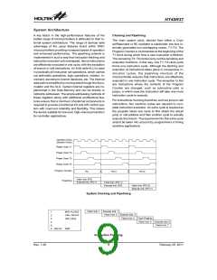
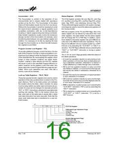
The following diagram illustrates the addressing/data
flow of the look-up table:
P
r
o
g
r
a
m
C
o
u
n
t
e
r
H
i
g
h
B
y
t
e
r o
P
g
r
a
m
M
e
m
o
r
y
T
B
L
P
·
Location 014H
This internal vector is used by the Multi-function Inter-
rupt 0. The Multi-function Interrupt 0 vector is shared
by the SPI/I2C and the C/R to F converter interrupt.
When an interrupt signal is generated, the program
will jump to this location and begin execution if the in-
terrupt is enabled and the stack is not full.
T
B
L
H
S
p
e
c
i
f
i
e
d
T
a
b
l
e
C
o
t n e t
h
T
a
b
l
e
C
o
n
t
e
n
t
s
H
i
g
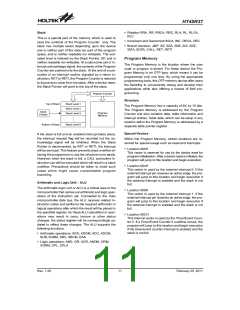
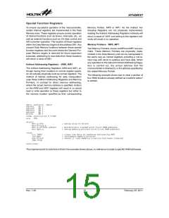
Table Location Bits
Instruction
b11
b10
b9
b8
PC8
1
b7
@7
@7
b6
@6
@6
b5
@5
@5
b4
b3
b2
@2
@2
b1
b0
TABRDC[m]
TABRDL [m]
PC11 PC10 PC9
@4
@4
@3
@3
@1
@1
@0
@0
1
1
1
Table Location
Note: PC11~PC8: Current Program Counter bits @7~@0: Table Pointer TBLP bits
Rev. 1.20
12
February 25, 2011
图片预览")
 HOLTEK [ HOLTEK SEMICONDUCTOR INC ]