HT45R37
·
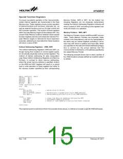
Stack
Rotation RRA, RR, RRCA, RRC, RLA, RL, RLCA,
RLC
This is a special part of the memory which is used to
save the contents of the Program Counter only. The
stack has multiple levels depending upon the device
and is neither part of the data nor part of the program
space, and is neither readable nor writeable. The acti-
vated level is indexed by the Stack Pointer, SP, and is
neither readable nor writeable. At a subroutine call or in-
terrupt acknowledge signal, the contents of the Program
Counter are pushed onto the stack. At the end of a sub-
routine or an interrupt routine, signaled by a return in-
struction, RET or RETI, the Program Counter is restored
to its previous value from the stack. After a device reset,
the Stack Pointer will point to the top of the stack.
·
·
Increment and Decrement INCA, INC, DECA, DEC
Branch decision, JMP, SZ, SZA, SNZ, SIZ, SDZ,
SIZA, SDZA, CALL, RET, RETI
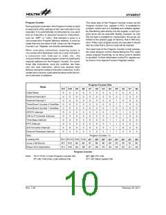
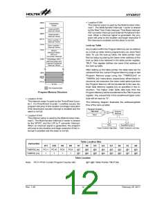
Program Memory
The Program Memory is the location where the user
code or program is stored. For these device the Pro-
gram Memory is an OTP type, which means it can be
programmed only one time. By using the appropriate
programming tools, this OTP memory device offer users
the flexibility to conveniently debug and develop their
applications while also offering a means of field pro-
gramming.
P
r
o
g
r
a
m
Structure
T
o
p
o
f
S
S
S
S
t
t
t
t
a
a
a
a
c
c
c
c
k
k
k
k
L
L
L
e
e
e
v
v
v
e
e
e
l
l
l
1
2
3
The Program Memory has a capacity of 4K by 15 bits.
The Program Memory is addressed by the Program
Counter and also contains data, table information and
interrupt entries. Table data, which can be setup in any
location within the Program Memory, is addressed by a
separate table pointer register.
S
t
a
c
k
P
r
o
g
r
a
P
o
i
n
t
e
r
M
e
m
o
r
B
o
t
t
o
m
o
S
f
t
a
S
c
t
k
a
c
L
k
e
v
e
l
6
Special Vectors
If the stack is full and an enabled interrupt takes place,
the interrupt request flag will be recorded but the ac-
knowledge signal will be inhibited. When the Stack
Pointer is decremented, by RET or RETI, the interrupt
will be serviced. This feature prevents stack overflow al-
lowing the programmer to use the structure more easily.
However, when the stack is full, a CALL subroutine in-
struction can still be executed which will result in a stack
overflow. Precautions should be taken to avoid such
cases which might cause unpredictable program
branching.
Within the Program Memory, certain locations are re-
served for special usage such as reset and interrupts.
·
Location 000H
This vector is reserved for use by the device reset for
program initialisation. After a device reset is initiated, the
program will jump to this location and begin execution.
·
Location 004H
This vector is used by the external interrupt 0. If the
external interrupt pin receives an active edge, the pro-
gram will jump to this location and begin execution if
the external interrupt is enabled and the stack is not
full.
Arithmetic and Logic Unit - ALU
The arithmetic-logic unit or ALU is a critical area of the
microcontrollerthat carries out arithmetic and logic oper-
ations of the instruction set. Connected to the main
microcontroller data bus, the ALU receives related in-
struction codes and performs the required arithmetic or
logical operations after which the result will be placed in
the specified register. As these ALU calculation or oper-
ations may result in carry, borrow or other status
changes, the status register will be correspondingly up-
dated to reflect these changes. The ALU supports the
following functions:
·
Location 008H
This vector is used by the external interrupt 1. If the
external interrupt pin receives an active edge, the pro-
gram will jump to this location and begin execution if
the external interrupt is enabled and the stack is not
full.
·
Location 00CH
This internal vector is used by the Timer/Event Coun-
ter 0. If a Timer/Event Counter 0 overflow occurs, the
program will jump to this location and begin execution
if the timer/event counter interrupt is enabled and the
stack is not full.
·
Arithmetic operations: ADD, ADDM, ADC, ADCM,
SUB, SUBM, SBC, SBCM, DAA
·
Logic operations: AND, OR, XOR, ANDM, ORM,
XORM, CPL, CPLA
Rev. 1.20
11
February 25, 2011
图片预览")
 HOLTEK [ HOLTEK SEMICONDUCTOR INC ]