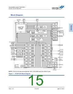
ꢃꢅ-bit �RM Coꢁtex™-Mꢃ MCU
HTꢃꢅF1ꢅ51/51B/5ꢅ/5ꢃ
Watchdog Timer
12-bit down counter with 3-bit prescaler
▀
▀
▀
▀
Interrupt or reset event for the system
Programmable watchdog timer window function
Write protection function
The Watchdog Timer is a hardware timing circuitry that can be used to detect system failures due
to software malfunctions. It includes a 12-bit down-counting counter, a prescaler, a WDT counter
value register, a WDT delta value register, interrupt related circuits, WDT operation control
circuitry and the WDT protection mechanism. The Watchdog Timer can be operated in an interrupt
mode or a reset mode. The Watchdog Timer will generate an interrupt or a reset when the counter
counts down and reaches a zero value. If the software does not reload the counter value before
the Watchdog Timer underflow occurs, an interrupt or a reset will be generated when the counter
underflows. In addition, an interrupt or reset is also generated if the software reloads the counter
when the counter value is greater than or equal to the WDT delta value. That means the counter
must be reloaded within a limited timing window using a specific method. The Watchdog Timer
counter can be stopped while the processor is in the debug mode. The register write protection
function can be enabled to prevent it from changing the configuration of the Watchdog Timer
unexpectedly.
Real Time Clock
32-bit up-counter with a programmable prescaler
▀
▀
▀
Alarm function
Interrupt and Wake-up event
The Real Time Clock, RTC, circuitry includes the APB interface, a 32-bit up-counter, a control
register, a prescaler, a compare register and a status register. Most of the RTC circuits are located
in the Backup Domain except for the APB interface. The APB interface is located in the VDD18
domain. Therefore, it is necessary to be isolated from the ISO signal that comes from the power
control unit when the VDD18 domain is powered off, i.e., when the device enters the Power-Down
mode. The RTC counter is used as a wakeup timer to generate a system resume from the
Power-Down mode.
Rev. 1.10
11 of ꢃ5
�ꢀꢁiꢂ 1ꢃꢄ ꢅ01ꢅ

 HOLTEK [ HOLTEK SEMICONDUCTOR INC ]