ICL7135
9.
DESCRIPTION OF DIGITAL CIRCUITS
• RUN/HOLD Input
When RUN/HOLD is high or open, the device continuously performs measurement cycles every 40002 clock pulses.
When this input is taken low, the integrated circuit continues to perform the ongoing measurement cycle and then hold
the conversion reading for as long as the terminal is held low. When the terminal is held low after completion of a
measurement cycle, a short positive pulse (greater than 300 ns) initiates a new measurement cycle. When this positive
pulse occurs before the completion of a measurement cycle, it will not be recognized. The first STROBE pulse, which
occurs 101 counts after the end of a measurement cycle, is an indication of the completion of a measurement cycle.
Thus, the positive pulse could be used to trigger the start of a new measurement after the first STROBE pulse.
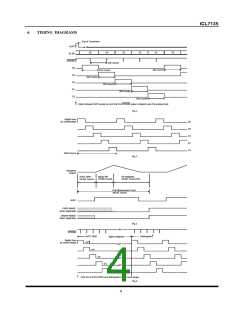
• STROBE Output
Negative going pulses from this output transfer the BCD conversion data to external latches, UARTs, or
microprocessors. At the end of the measurement cycle, STROBE goes high and remains high for 201 counts. The most
significant digit (MSD) BCD bits are placed on the BCD terminals. After the first 101 counts, halfway through the
duration of output D1-D5 going high, the STROBE terminal goes low for 1/2 clock pulse width. The placement of the
STROBE pulse at the midpoint of the D5 high pulse allows the information to be latched into an external device on
either a low-level or an edge. Such placement of the STROBE pulse also ensures that the BCD bits for the second MSD
are not yet competing for the BCD lines and latching of the correct bits is ensured.
The above process is repeated for the second MSD and the D4 output. Similarly, the process is repeated through the
least significant digit (LSD). Subsequently, inputs D5 through D1 and the BCD lines continue scanning without the
inclusion of STROBE pulses. This subsequent continuous scanning causes the conversion results to be continuously
displayed. Such subsequent scanning does not occur when an over-range condition occurs.
• BUSY Output
The BUSY output goes high at the beginning of the signal integrate phase. BUSY remains high until the first clock
pulse after zero crossing or at the end of the measurement cycle when an over-range condition occurs. It is possible to
use the BUSY terminal to serially transmit the conversion result. Serial transmission can be accomplished by ANDing
the BUSY and CLOCK signals and transmitting the ANDed output. The transmitted output consists of 10,001 clock
pulses, which occur during the signal integrate phase, and the number of clock pulses that occur during the deintegrate
phase. The conversion result can be obtained by subtracting 10,001 from the total number of clock pulses.
• OVER-RANGE Output
When an over-range condition occurs, this terminal goes high after the BUSY signal goes low at the end of the
measurement cycle. As previously noted, the BUSY signal remains high until the end of the measurement cycle when
an over-range condition occurs. The OVER RANGE output goes high at the end of BUSY and goes low at the
beginning of the deintegrate phase in the next measurement cycle.
• UNDER-RANGE Output
At the end of the BUSY signal, this terminal goes high when the conversion result is less than or equal to 9% (count of
1800) of the full-scale range. The UNDER RANGE output is brought low at the beginning of the signal integrate phase
of the next measurement cycle.
• POLARITY Output
The POLARITY output is high for a positive input signal and updates at the beginning of each deintegrate phase. The
polarity output is valid for all inputs including ±0 and OVER RANGE signals.
• Digit-Drive (D1, D2, D4 and D5) Outputs
Each digit-drive output (D1 through D5) sequentially goes high for 200 clock pulses. This sequential process is
continuous unless an over-range occurs. When an over-range occurs, all of the digit-drive outputs are blanked from the
end of the strobe sequence until the beginning of the deintegrate phase (when the sequential digit-drive activation
begins again). The blanking activity during an over-range condition can cause the display to flash and indicate the over-
range condition.
• BCD Outputs
The BCD bits (B1, B2, B4 and B8) for a given digit are sequentially activated on these outputs. Simultaneously, the
appropriate digit-drive line for the given digit is activated.
6

 HN [ NANJING HONANO ELECTRONIC CO., LTD. ]