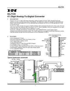
ICL7135
3.
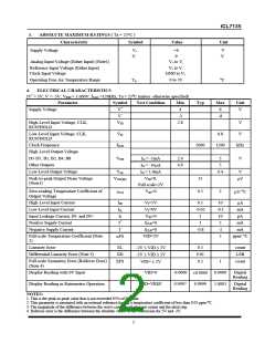
ABSOLUTE MAXIMUM RATINGS ( Ta = 25°C )
Characteristic Symbol
Value
Unit
Supply Voltage
V+
V-
+6
-9
V
V
Analog Input Voltage (Either Input) (Note1)
Reference Input Voltage (Either Input)
Clock Input Voltage
V+ to V-
V+ to V-
GND to V+
Operating Free-Air Temperature Range
TA
0 to 70
oC
4.
ELECTRICAL CHARACTERISTICS
(V+ = 5V; V- = -5V; VREF = 1.000V; fCLK =120kHz, Ta = 25oC (unless otherwise specified)
Parameter
Symbol
V+
Test Condition
Min
4
Typ
Max
Unit
Supply Voltage
6
V
V-
-3
-8
High-Level Input Voltage, CLK,
RUN/HOLD
VIH
2.8
V
V
Low-Level Input Voltage, CLK,
RUN/HOLD
VIL
0.8
Clock Frequency
fCLK
2000
1200
kHz
High-Level Output Voltage
D1-D5, B1, B2, B4, B8
Other Outputs
VOH
IO = -1mA
IO = -10µA
IO = 1.6mA
VID=0,
2.4
4,9
5
5
V
Low-Level Output Voltage
VOL
0.4
V
Peak-to-peak Output Noise Voltage
(Note1)
VON(PP)
15
µV
Full scale=2V
VID=0
αVO
µV/ oC
Zero-reading Temperature Coefficient of
Output Voltage
0.5
2
High-Level Input Current
Low-Level Input Current
Input Leakage Current, IN- and IN+
Positive Supply Current
IIH
IIL
II
I+
I-
VI=5V
VI=0V
VID=0
0.1
-0.02
1
10
-0.1
10
2
µA
mA
pA
fCLK=0
fCLK=0
VID=2V
1
mA
Negative Supply Current
-0.8
-2
mA
Full-scale Temperature Coefficient (Note
2)
5
ppm/ °C
αFS
Linearity Error
EL
ED
0.5
0.01
0.5
count
LSB
-2V ≤ VID ≤ 2V
-2V ≤ VID ≤ 2V
VID= ± 2V
Differential Linearity Error (Note 3)
Full-scale Symmetry Error (Rollover Error)
(Note 4)
EFS
1
count
Display Reading with 0V Input
VID=0
-0.0000
0.9997
0.0000
1.0003
Digital
Reading
±0.0000
Display Reading in Ratiometric Operation
VID=VREF
0.9999
Digital
Reading
NOTES:
1. This is the peak-to-peak value that is not exceeded 95% of the time.
2. This parameter is measured with an external reference having a temperature coefficient of less than 0.01 ppm/oC.
3. The magnitude of the difference between the worst case step of adjacent counts and the ideal step.
4. Rollover error is the difference between the absolute values of the conversion for 2V and -2V.
2

 HN [ NANJING HONANO ELECTRONIC CO., LTD. ]