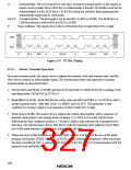
13.3.4 Slave Transmit Operation
In slave transmit mode, the slave device outputs the transmit data, and the master device outputs
the transmit clock and returns an acknowledge signal. The transmit procedure and operations in
slave transmit mode are described below.
1. Set bits MLS and WAIT in ICMR and bits MST, TRS, ACK, and CKS2 to CKS0 in ICCR
according to the operating mode. Set bit ICE in ICCR to 1, establishing slave receive mode.
2. After the slave device detects a start condition, if the first byte matches its slave address, at the
ninth clock pulse the slave device drives SDA low to acknowledge the transfer. At the same
time, IRIC is set to 1 in ICSR, generating an interrupt. If the eighth data bit (R/W) is 1, the
TRS bit is set to 1 in ICCR, automatically causing a transition to slave transmit mode. The
slave device holds SCL low from the fall of the transmit clock until data is written in ICDR.
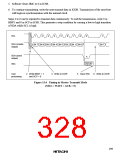
3. Software clears IRIC to 0 in ICSR.
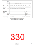
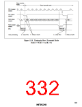
4. Write data in ICDR. The slave device outputs the written data serially in step with the clock
output by the master device, with the timing shown in figure 13.8.
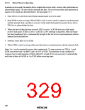
5. When one byte of data has been transmitted, at the rise of the ninth transmit clock pulse IRIC
is set to 1 in ICSR. If IEIC is set to 1 in ICCR, a CPU interrupt is requested. The slave device
holds SCL low from the fall of the transmit clock until data is written in ICDR. The master
device drives SDA low at the ninth clock pulse to acknowledge the data. The acknowledge
signal is stored in ACKB in ICSR, and can be used to check whether the transfer was carried
out normally.
6. Software clears IRIC to 0 in ICSR.
7. To continue transmitting, write the next transmit data in ICDR.
Steps 5 to 7 can be repeated to transmit continuously. To end the transmission, write H'FF in
ICDR. When a stop condition is detected (a low-to-high transition of SDA while SCL is high),
BBSY will be cleared to 0 in ICSR.
302

 HITACHI [ HITACHI SEMICONDUCTOR ]