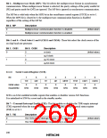
Bit 6—Receive Data Register Full (RDRF): This bit indicates when one character has been
received and transferred to RDR.
Bit 6: RDRF
Description
0
To clear RDRF, the CPU must read RDRF after it has been set to 1, then write
a 0 in this bit.
(Initial value)
1
This bit is set to 1 when one character is received without error and transferred
from RSR to RDR.
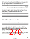
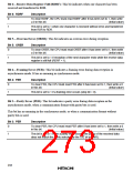
Bit 5—Overrun Error (ORER): This bit indicates an overrun error during reception.
Bit 5: ORER
Description
0
To clear ORER, the CPU must read ORER after it has been set to 1, then write
a 0 in this bit.
(Initial value)
1
This bit is set to 1 if reception of the next character ends while the receive data
register is still full (RDRF = 1).
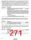
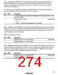
Bit 4—Framing Error (FER): This bit indicates a framing error during data reception in
asynchronous mode. It has no meaning in synchronous mode.
Bit 4: FER
Description
0
To clear FER, the CPU must read FER after it has been set to 1, then write a 0
in this bit.
(Initial value)
1
This bit is set to 1 if a framing error occurs (stop bit = 0).
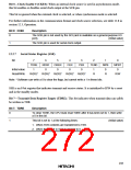
Bit 3—Parity Error (PER): This bit indicates a parity error during data reception in the
asynchronous mode, when a communication format with parity bits is used.
This bit has no meaning in the synchronous mode, or when a communication format without
parity bits is used.
Bit 3: PER
Description
0
To clear PER, the CPU must read PER after it has been set to 1, then write a 0
in this bit.
(Initial value)
1
This bit is set to 1 when a parity error occurs (the parity of the received data
does not match the parity selected by the O/E bit in SMR).
244

 HITACHI [ HITACHI SEMICONDUCTOR ]