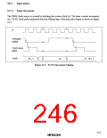
Positive Logic (OS = 0):
1. When (OE = 0)—(a) in Figure 10.3
The timer count is held at H'00 and PWM output is inhibited. [Pin 46 (for PW0) or pin 47 (for
PW1) is used for port 4 input/output, and its state depends on the corresponding port 4 data
register and data direction register.] Any value (such as N in figure 10.3) written in the DTR
becomes valid immediately.
2. When (OE = 1)
a. The timer counter begins incrementing. The PWM output goes high when TCNT changes
from H'00 to H'01, unless DTR = H'00. [(b) in figure 10.3]
b. When the count passes the DTR value, the PWM output goes low. [(c) in figure 10.3]
c. If the DTR value is changed (by writing the data “M” in figure 10.3), the new value
becomes valid after the timer count changes from H'F9 to H'00. [(d) in figure 10.3]
Negative Logic (OS = 1)—(e) in Figure 10.3: The operation is the same except that high and low
are reversed in the PWM output. [(e) in figure 10.3]
10.4
Application Notes
Some notes on the use of the PWM timer module are given below.
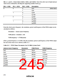
1. Any necessary changes to the clock select bits (CKS2 to CKS0) and output select bit (OS)
should be made before the output enable bit (OE) is set to 1.
2. If the DTR value is H'00, the duty cycle is 0% and PWM output remains constant at 0.
If the DTR value is H'FA to H'FF, the duty cycle is 100% and PWM output remains constant at
1.
(For positive logic, 0 is low and 1 is high. For negative logic, 0 is high and 1 is low.)
219

 HITACHI [ HITACHI SEMICONDUCTOR ]