欢迎访问ic37.com |
会员登录 免费注册
发布采购

HD64F2134TF20 参数 Datasheet PDF下载

HD64F2134TF20图片预览
型号: HD64F2134TF20
PDF下载: 下载PDF文件 查看货源
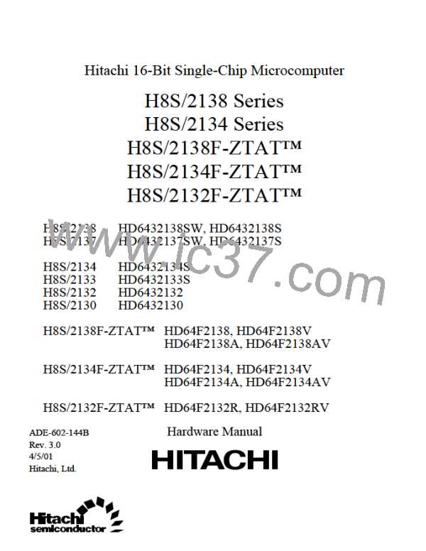
内容描述: [Microcontroller, 16-Bit, FLASH, H8S/2000 CPU, 16MHz, CMOS, PQFP80, PLASTIC, TQFP-80]
分类和应用: 微控制器外围集成电路
文件页数/大小: 993 页 / 4535 K
品牌: HITACHI [ HITACHI SEMICONDUCTOR ]
 浏览型号HD64F2134TF20的Datasheet PDF文件第13页浏览型号HD64F2134TF20的Datasheet PDF文件第14页浏览型号HD64F2134TF20的Datasheet PDF文件第15页浏览型号HD64F2134TF20的Datasheet PDF文件第16页浏览型号HD64F2134TF20的Datasheet PDF文件第18页浏览型号HD64F2134TF20的Datasheet PDF文件第19页浏览型号HD64F2134TF20的Datasheet PDF文件第20页浏览型号HD64F2134TF20的Datasheet PDF文件第21页  
12.3
12.4
12.5
12.6
Timer Counter (TCNT).........................................................................................
Time Constant Register A (TCORA) ...................................................................
Time Constant Register B (TCORB) ...................................................................
Timer Control Register (TCR) .............................................................................
Timer Control/Status Register (TCSR) ................................................................
Serial/Timer Control Register (STCR).................................................................
System Control Register (SYSCR).......................................................................
Timer Connection Register S (TCONRS) ............................................................
Input Capture Register (TICR) [TMRX Additional Function].............................
Time Constant Register C (TCORC) [TMRX Additional Function]...................
Input Capture Registers R and F (TICRR, TICRF)
[TMRX Additional Functions] ............................................................................
12.2.12 Timer Input Select Register (TISR) [TMRY Additional Function].....................
12.2.13 Module Stop Control Register (MSTPCR)...........................................................
Operation ...........................................................................................................................
12.3.1 TCNT Incrementation Timing..............................................................................
12.3.2 Compare-Match Timing .......................................................................................
12.3.3 TCNT External Reset Timing...............................................................................
12.3.4 Timing of Overflow Flag (OVF) Setting..............................................................
12.3.5 Operation with Cascaded Connection ..................................................................
12.3.6 Input Capture Operation .......................................................................................
Interrupt Sources................................................................................................................
8-Bit Timer Application Example .....................................................................................
Usage Notes .......................................................................................................................
12.6.1 Contention between TCNT Write and Clear ........................................................
12.6.2 Contention between TCNT Write and Increment.................................................
12.6.3 Contention between TCOR Write and Compare-Match ......................................
12.6.4 Contention between Compare-Matches A and B .................................................
12.6.5 Switching of Internal Clocks and TCNT Operation.............................................
12.2.1
12.2.2
12.2.3
12.2.4
12.2.5
12.2.6
12.2.7
12.2.8
12.2.9
12.2.10
12.2.11
293
294
295
295
299
302
303
303
304
304
305
305
306
307
307
308
310
310
311
312
314
315
315
315
316
317
318
318
Section 13 Timer Connection [H8S/2138 Series]
...................................................... 321
13.1 Overview............................................................................................................................
13.1.1 Features.................................................................................................................
13.1.2 Block Diagram......................................................................................................
13.1.3 Input and Output Pins...........................................................................................
13.1.4 Register Configuration .........................................................................................
13.2 Register Descriptions.........................................................................................................
13.2.1 Timer Connection Register I (TCONRI)..............................................................
13.2.2 Timer Connection Register O (TCONRO)...........................................................
13.2.3 Timer Connection Register S (TCONRS) ............................................................
13.2.4 Edge Sense Register (SEDGR).............................................................................
13.2.5 Module Stop Control Register (MSTPCR)...........................................................
13.3 Operation ...........................................................................................................................
viii
321
321
322
323
324
324
324
327
329
331
333
334