ICL8038
Typical Applications
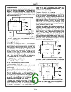
The sine wave output has a relatively high output impedance
(1kΩ Typ). The circuit of Figure 6 provides buffering, gain
and amplitude adjustment. A simple op amp follower could
also be used.
+10V
1N457
DUTY CYCLE
15K
0.1µF
1K
4.7K
V+
4.7K
R
R
B
A
AMPLITUDE
100K
5
4
6
9
3
2
4
5
6
7
8
2
+
741
-
10K
FREQ.
8
ICL8038
ICL8038
20K
10
11
12
4.7K
10
11
DISTORTION
100K
0.0047µF
20K
≈15M
C
-10V
V-
IGURE 8. VARIABLE AUDIO OSCILLATOR, 20Hz TO 20kHzY
FIGURE 6. SINE WAVE OUTPUT BUFFER AMPLIFIERS
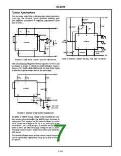
With a dual supply voltage the external capacitor on Pin 10 can
be shorted to ground to halt the ICL8038 oscillation. Figure 7
shows a FET switch, diode ANDed with an input strobe signal
to allow the output to always start on the same slope.
V+
R
R
B
15K
A
4
5
7
8
9
ICL8038
1N914
2
11
10
1N914
C
2N4392
-15V
STROBE
100K
OFF
+15V (+10V)
-15V (-10V)
ON
FIGURE 7. STROBE TONE BURST GENERATOR
To obtain a 1000:1 Sweep Range on the ICL8038 the volt-
age across external resistors R and R must decrease to
A
B
nearly zero. This requires that the highest voltage on control
Pin 8 exceed the voltage at the top of R and R by a few
A
B
hundred mV. The Circuit of Figure 8 achieves this by using a
diode to lower the effective supply voltage on the ICL8038.
The large resistor on pin 5 helps reduce duty cycle variations
with sweep.
The linearity of input sweep voltage versus output frequency
can be significantly improved by using an op amp as shown
in Figure 9.
8-159

 HARRIS [ HARRIS CORPORATION ]