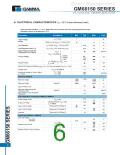
ELECTRICAL CHARACTERISTICS (T = 25°C unless otherwise noted)
A
Unless otherwise specified: T = 25°C; Bold values are guaranteed across the operating temperature range.
J
Adjustable versions are programmed to 5.0V.
Typ
Parameter
Conditions
Min
Max
Unit
-1
I
O
= 10 mA
1
%
Output Voltage
(Note2)
10mA
I
O
I
,(V
FL
+ 1V)
V
26V
-2
2
%
%
OUT
IN
I
= 10mA, (V
+ 1V)
V
26V
Line Regulation
0.06
0.20
20
0.5
1.0
100
O
OUT
IN
V
IN
= V
+ 5V, 10mA
I
I
OUT FL
Load Regulation (Note 2, 6)
%
OUT
Output Voltage change with
Temperature Coef. (Note 6)
DV
OUT
/ DT
ppm/°C
DV
OUT =
-1% (Note 3)
I
= 100mA
= 750mA
= 1.5A
O
80
200
Dropout Voltage
mV
I
220
350
O
O
I
600
20
I
O
= 750mA, V = V
IN
+ 1V
OUT
8
Ground Current
mA
I
O
= 1.5A
22
Ground Pin Current at Dropout I
V
= 0.5V less than specified V
, I
OUT OUT
= 10mA
2.0
mA
IN
GNDDO
V
OUT
,= 0V (Note 4)
Current Limit
Output Noise Voltage e , (10Hz to 100Hz)
n
2.1
3.5
A
C = 10µF
L
400
260
µV (rms)
C = 33µF
L
I
= 100mA
O
Reference GM66152
V
V
1.228
1.240
1.252
Reference Voltage
1.215
1.265
Reference Voltage
(Note 8)
1.203
1.277
V
40
80
Adjust Pin Bias Current
nA
120
Reference Voltage change with
Temperature Coef.
(Note 7)
ppm/°C
20
Adjust Pin Bias Current change with
Temperature
0.1
nA/°C
Flag Output (Error Comparator) GM66151/ GM66153
0.01
220
60
1
V
= 26V
Output Leakage Current
µA
mV
mV
mV
mV
OH
2
Device set for 5V, V = 4.5V
IN
300
400
Output Low Voltage
I
OL
= 250µA
40
Upper Treshold Voltage
Lower Treshold Voltage
Hysteresis
Device set for 5V(Note 9)
Device set for 5V(Note 9)
Device set for 5V(Note 9)
25
75
95
140
15
Enable Input GM66151 / GM66152
Input Logic Voltage
Low (OFF)
0.8
V
High (ON)
2.4
100
600
750
2.5
V
EN
= 26V
µA
Enable Pin Input Current
V
EN
= 0.8V
µA
µA
5.0
10
Regulator Output Current In Shutdown
(Note10)
500
6

 GAMMA [ GAMMA MICROELECTRONICS INC. ]