Capacitor Requirements
The adjustable regulator versions, GM66152 and
GM66153, allow programming the output voltage
anywhere between 1.25V and the 26V maximum op-
erating rating of the family. Two resistors are used.
For stability and minimum output noise, a capacitor on
the regulator output is necessary. The value of this ca-
pacitor is dependent upon the output current; lower cur-
rents allow smaller capacitors. GM66150 regulators
are stable with the minimum capacitor value of 10µF at
full load. This capacitor needs not be an expensive low
ESR type: aluminum electrolytics are adequate. In fact,
extremely low ESR capacitors may contribute to insta-
bility. Tantalum capacitors are recommended for sys-
tems where fast load transient response is important.
Where the regulator is powered from a source with a
high AC impedance, a 0.1µF capacitor connected be-
tween Input and GND is recommended. This capacitor
should has good characteristics to above 250kHz.
Resistors can be quite large, up to 1MW, because of
the very high input impedance and low bias current
of the sense comparator: The resistor values are cal-
culated by:
V
OUT
R1 = R2 (
-1)
1.240
where V is the desired output voltage.
O
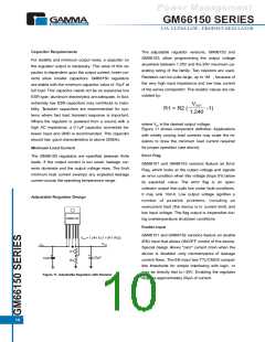
Figure 11 shows component definition. Applications
with widely varying load currents may scale the re-
sistors to draw the minimum load current required
for proper operation (see above).
Minimum Load Current
Error Flag
The GM66150 regulators are specified between finite
loads. If the output current is too small, leakage cur-
rents dominate and the output voltage rises. The 5mA
minimum load current swamps any expected leakage
current across the operating temperature range.
GM66151 and GM66153 versions feature an Error
Flag, which looks at the output voltage and signals
an error condition when this voltage drops 5% below
its expected value. The error flag is an open-
collector output that pulls low under fault conditions.
It may sink 10mA. Low output voltage signifies a
number of possible problems, including an
overcurrent fault (the device is in current limit) and
low input voltage. The flag output is inoperative dur-
ing overtemperature shutdown conditions.
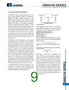
Adjustable Regulator Design
GM66152
Enable Input
GM66151 and GM66152 versions feature an enable
(EN) input that allows ON/OFF control of the device.
Special design allows "zero" current drain when the
device is disabled -only microamperes of leakage
current flows. The EN input has TTL/CMOS compat-
ible thresholds for simple interfacing with logic, or
may be directly tied to 30V. Enabling the regulator
requires approximately 20µA of current.
VOUT= 1.24V X [1 + (R1 /R2)]
VOUT
VIN
R1
+
+
22µF
10µF
R2
Figure 11. Adjustable Regulator with Resistor
10

 GAMMA [ GAMMA MICROELECTRONICS INC. ]