Application Notes
L1
1
The resistor value in Kohms for the GPH5V0-30 and
GPH5V0-40 is:
2
48V
In (+)
In (–)
°
+
C1
270µF
63V
C2
1µF
100V
(VO – 5.0)
RTRIM = —————— + 1.0KΩ
1.0
°
3
48V RTN
4
80
UH
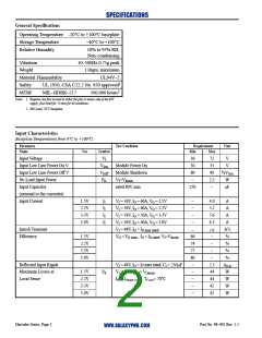
Thermal Considerations:
+
In (+)
In (–)
+
DC/DC
Converter
Thermal considerations are an important factor in the
reliable operation of the converter. The maximum
operating baseplate temperature is 100°C. The
maximum recommended operating baseplate
temperature is 90°C. The baseplate temperature is a
function of the losses within the converter, the converter
ambient temperature, and airflow across the heat sink.
Input
–
Output
RLOAD
P Enable
Case
–
C3
C4
1µF
100V
1µF
100V
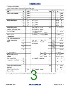
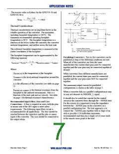
L1
C1
Common Mode Inductor
270µF, 63V Aluminum Electrolytic Capacitor
The reference baseplate temperature is measured at the
center coordinates of the baseplate.
C2-C4 1µF, 100V Ceramic capacitor
The baseplate temperature can be approximated by the
following equation:
Paralleling Converters: Two to five converters can be
paralleled as long as the following conditions are met.
When all of the converters are from the same
manufacturer the current share pins must be connected
together and the sync pins may be connected together if
desired.
1 – η
TBASEPLATE = POUTPUT*—————*RBASEPLATE
+ TAMBIENT
AMBIENT
-
η
Where:
T
BASEPLATE is the temperature of the baseplate.
When converters from different manufacturers are
paralleled, the current share pins must be connected
together and the sync pins must NOT be connected
together.
TAMBIENT is the local ambient temperature around the
converter
η is the efficiency of the converter (see table on page
2)
The maximum output current for paralleled
configurations is shown in the table on page 5.
R
BASEPLATE-AMBIENT is the thermal resistance from the
When a converter fails in a parallel configuration it may
or may not deassert its MODOK_L signal.
baseplate to the ambient environment. This is a
function of the heat sink and air velocity. See table
on page 5 for thermal resistance characteristics.
It should also be noted that current for the control
circuit in the converter flows through the – SENSE lead.
For this reason it is important to keep the impedance
between the – SENSE pins on the converters in a
parallel configuration low. The best approach is to
connect the – SENSE pins together with as large of an
etch as possible (250 milliohms maximum
Recommended Input Filter, Fuse and Case
Connections: A fuse is required in series with the plus
or minus side of the 48V input to meet safety
requirements. The following input filter circuit is
recommended for all applications. The fuse should be
inserted between the capacitors and the plus or minus
input of the converter. The case should be connected to
the output return.
recommended) and then run a single set of sense leads
to the remote sense point at the load.
Hercules Series, Page 7
Part No. 98–002 Rev. 1.1
WWW.GALAXYPWR.COM

 GALAXY [ GALAXY POWER, INC. ]