Specifications
Control Signal Characteristics
Parameter
Name
Test Condition
Requirement
Unit
Symbol
Min
Max
Enable_L
VENABLE
Enable_L asserted
0
4.5
–
0.8
5.5
-1.0
100
–
V
V
Function Control
Voltage (Secondary Side)
Enable
Enable_L de-asserted
Source Current (VENABLE = 0.8V)
Enable_L asserted
mA
Ω
RENABLE
–
Function Control
Resistance (Secondary Side)
OTW–L
Enable_L de-asserted
200K
–
Ω
Source Current (RENABLE = 100Ω)
OTW_L asserted, VS = 5V, RL = 50Ω
OTW_L de-asserted, VS = 15V
OTW_L asserted, VS = 5V, RL =5K
VI = 48V, VO = rated VO,
-1.0
20
mA
mA
µA
V
I SINK
I LEAKAGE
VL
8
Overtemperature Warning
–
10
–
0.2
–
TOTW
500
ms
-L
Time delay
IO= Rated IO , Fan-off early warning time
max
before converter shuts down due to thermal
overload
MODOK_L
I LEAKAGE
ISINK
MODOK_L de-asserted, VS = 15V
MODOK_L asserted, VS = 5V, RL = 50Ω
MODOK_L asserted, VS = 5V, RL = 5K
–
8
–
10
20
µA
mA
V
VL
0.2
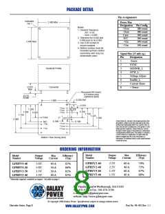
Maximum Output Load Current (IOP) vs Number of Converters
No. of Converters
1.5V & 2.2V
60A
3.3V
50A
5.0V
40A
1
2
3
4
5
117A
87.75A
130.5A
173.25A
216A
58.5A
87.0A
115.5A
144A
174A
231A
288A
Thermal Characteristics (ΘCA)
Air Velocity
(m/s)
Thermal Resistance (Baseplate to Ambient)
°
C/W
0.9" Heatsink
1.4" Heatsink
0.5
1.0
1.5
2.0
2.5
3.0
1.9
1.6
1.4
1.3
2.1
1.3
1.1
1.0
0.9
Hercules Series, Page 5
Part No. 98–002 Rev. 1.1
WWW.GALAXYPWR.COM

 GALAXY [ GALAXY POWER, INC. ]