Specifications
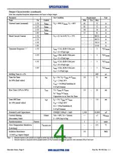
Output Characteristics (continued)
Over the complete baseplate temperatures and input voltage ranges.
Parameter
Name
Test Condition
Requirement
Unit
Var
1.5V
2.2V
3.3V
5.0V
1.5V
2.2V
3.3V
5.0V
1.5V
Symbol
Min
61
61
46
37
–
Typ
Max
Current Limit (nominal)
Short Circuit Current
Transient Response 1, 2
IO
IO
IO
IO
VO = 90% VO
, VI = 48V
nom
72
72
A
A
A
A
A
A
A
A
lim
lim
lim
lim
54
42
VO = 0.2 to 0.4V, VI = 72V
–
–
–
–
–
80/55
80/55
70/55
55/45
3
–
–
–
I
=15A, di/dt=10A/µsec
–
%VO
step
nom
nom
nom
nom
CO = 35-470µf caps
=28A, di/dt=28A/µsec
2.2V
3.3V
5.0V
I
–
–
–
–
–
–
3
3
3
%VO
%VO
%VO
step
CO = 35-470µf caps
=12A, di/dt=10A/µsec
I
step
CO = 10-470µf caps
=10A, di/dt=10A/µsec
I
step
CO = 5-470µf caps
Settling Time to ±1%
Turn On Time
–
–
–
600
75
µs
t
IO = 5A, VI= VI
to VI
max
10
ms
on
min
(to 90% final value)
C
C
= 250µf, 80V
in
= 10,000µf tantalum &
out
0.47µf Ceramic
Rise Time (10% to 90%)
T
VI= VI
to VI
10
–
–
–
20
ms
ms
rise
min
min
max
max
IO= IO
to IO
Capacitors as in Turn On Time
IO = 5A, VI to VI
Turn Off Time
t
2.0
off
min
max
(to 10% initial value)
C = 250µf, 80V
in
Co = 330µf tantalum &
0.47µf Ceramic
External Load Capacitance
Current Sharing
ESR@17,000µf = 2mΩ
Vin = 48V, Vo = Vonom
I = 10% Iop to Iop
1,500
—
18,800
µf
Ishare
±5
%IO
max
(Secondary Side)
Synchronization
Fanout
1
–
5
units
Over Temperature Shutdown
(Latching)
TBASEPLATE
–
125
°C
Isolation Resistance
(1500VDC) Input-Output
10
MΩ
Notes: 1. Transient response is for a positive or a negative current step within the range of 5% of Imax to Imax.
2. Transient response is measured with the specified number of 470µF tantalum external load capacitors with a maximum ESR of 55mΩ each.
Hercules Series, Page 4
Part No. 98–002 Rev. 1.1
WWW.GALAXYPWR.COM

 GALAXY [ GALAXY POWER, INC. ]