MB85RC64
■ DATA STRUCTURE
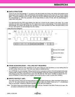
In the I2C bus, the acknowledge “L” is output on the 9th bit after the 8 bits of the device and address word
following the start condition. After confirming the acknowledge response at the slave, the I2C master outputs
8bits × 2 memory address to the I2C slave. When the memory address input ends, the slave again outputs
the acknowledge “L”. After this operation, the I/O data follows in units of 8 bits, with the acknowledge “L”
output after every 8bits.
It is determined by the R/W code whether the data line is driven by the master or the slave. For a write
operation the slave will accept 8bits from the master then send an acknowledge. If the master detects the
acknowledge, the master will transfer the next 8bits. For a read operation the slave will place 8bits on the
I2C bus, then wait for an acknowledge from the master.
• Data Structure Diagram
2
Start
1
2
3
4
5
6
7
8
9
1
..
..
SCL
SDA
ACK
A
1
0
1
0
R/W
S
A2 A1 A0
Access from master
Access from slave
S
A
Start Condition
ACK
■ FRAM ACKNOWLEDGE -- POLLING NOT REQUIRED
The MB85RC64 performs write operations at the same speed as read operations, so any waiting time for
an ACK polling* does not occur. The write cycle takes no additional time.
*: As to E2PROM, the Acknowledge Polling is performed as a progress check in the write programming step.
It places NAK condition on the bus as of “not acknowledged” during the writing programming period. The
busy status for the write programming is given from 9th ACK bit. That “done” condition is placed onto I2C
bus by E2PROM I2C device and your program had to poll the bus in order to sense that condition.
■ WRITE PROTECT (WP)
The entire memory array can be write protected using the Write Protect pin. When the Write Protect pin is
set to “H”, the entire memory map will be write protected. When the Write Protect pin is “L”, all addresses
may be overwritten. Reading is allowed regardless of the WP pin's High/Low.
Note : The Write Protect pin is pulled down internally to VSS pin, therefore if the Write Protect pin is open, the
pin status is detected as Low (write enabled).
DS05–13109–3E
7

 FUJITSU [ FUJITSU ]