MB3769A
1
fOSC ~
CT ~
0.8 x CT x RT
1
x
4
(tcycle - tP ) [pF] (RT: kΩ, tcycle, tP: ns)
0.8 x RT
4.5 - VL
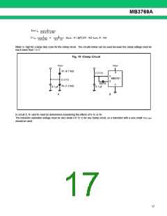
Make VL high for a large duty cycle for the clamp circuit. The circuits below can be used because the clamp voltage must be
much lower than 1.5 V.
Fig. 19 -Clamp Circuit
VREF
VREF
R1 (4.7 kΩ)
8
(1.2 V)
3
4
MB3761
(1.2 V)
820 Ω
0.1 µF
5
R2 (1.2 kΩ)
0.1 µF
A
B
In circuit A, R1 and R2 must be determined considering the effects of tP, R, or RT.
The transistor saturation voltage must be very small (<0.15 V) for any clamp circuit, so a transistor with a very small VCE (sat)
should be used.
17

 FUJITSU [ FUJITSU ]