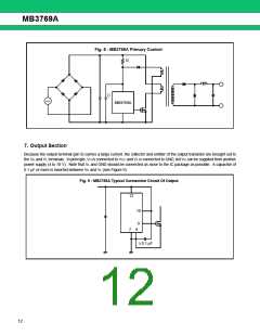
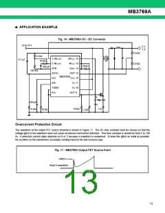
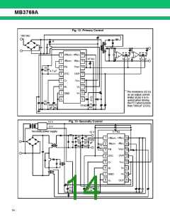
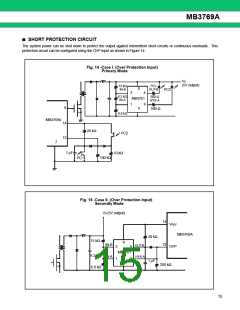
MB3769A
■ HOW TO SYNCHRONIZE WITH OUTSIDE CLOCK
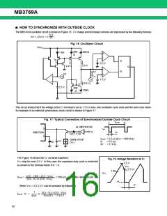
The MB3769A oscillator circuit is shown in Figure 16. CT charge and discharge currents are expressed by the following formula:
5 V
ICT = ±2 x I1 = ±
RT
Fig. 16 -Oscillator Circuit
VREF
500
Ω
500 Ω
1 kΩ
+
-
I1
S
R
3.5 V
2 x I1
2 x I1
Q
-
+
ICT
CT
RT
-
6
5
1.5 V
+
(4 x I1)
2.5 V
300
150Ω
Ω
This circuit shows that if the voltage at the CT terminal is set to 1.5 V or less, one oscillation cycle ends and the next cycle starts.
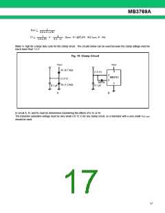
An example of an external synchronous clock circuit is shown in Figure 17.
Fig. 17 -Typical Connection of Synchronized Outside Clock Circuit
tcycle
ex. MB74HC04
5
VP
VP
tP
MB3769A
R(5.1 k Ω)
6
tcycle = 2.5 µs (fEXT = 400 kHz)
clamp circuit
(VL)
CT
tP
= 0.5 µs
RT
RT = 11 k Ω
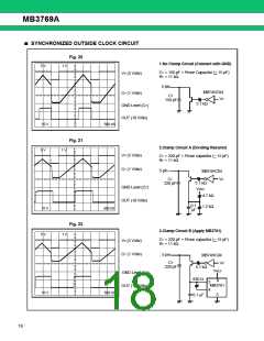
The Figure 18 shows the CT terminal waveform.
Fig. 18 -Voltage Waveform at CT
VTH may be near 2.5 V. In this case, the maximum duty cycle is restricted
as shown in the formula below if tP’ = 0.
3.5 V
VTH
.
( 2.5 V)
.
1.85
VCT
(3.5 - 1.85) + (3.5 - VTH)
(3.5 - VL ) + (3.5 - VTH )
Dmax=
≤ 59% (VL = 0 V: No clamp circuit)
VL
tP’
When VTH = 2.5 V, CT can be provided by followings.
1
(3.5 - VL) + (3.5 - VTH)
fOSC(3.5 - 1.5 ) x 2
tcycle - tP =
x
fOSC
16

 FUJITSU [ FUJITSU ]