MB3769A
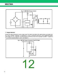
■ APPLICATION EXAMPLE
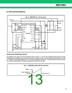
Fig. 10 - MB3769A DC - DC Convertor
12 to 18 V
5 V
1 A
3.6 kΩ
2.4 kΩ
3.3 kΩ
+IN (C) 16
IN (C) 15
VREF 14
OVP 13
1+IN (OP)
0.1 µF
10 kΩ
330 pF
2-IN (OP)
3FB
20 kΩ
100 kΩ
4DTC
5CT
MB3769A
VCC 12
VZ 11
6RT
VH 10
7GND
8VL
OUT 9
R
S
220 pF
C
10 kΩ
1 Ω
51 kΩ
18 kΩ
5.1 kΩ
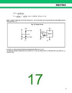
Overcurrent Protection Circuit
The waveform at the output FET source terminal is shown in Figure 11. The RC time constant must be chosen so that the
voltage glitch in the waveform does not cause erroneous overcurrent detection. This time constant is should be from 5 to 100
ns. A detection current value depends on R or C because a waveform is weakened. To keep this glitch as small as possible,
the rectifiers on the transformer secondary winding must be the fast-recovery type.
Fig. 11 - MB3769A Output FET Source Point
Glitch
Point S waveform
13

 FUJITSU [ FUJITSU ]