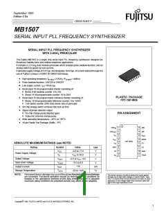
MB1507
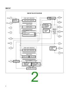
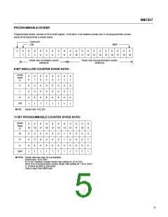
PROGRAMMABLE DIVIDER
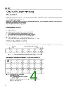
Programmable divider consists of 20-bit shift register, 19-bit latch, 8-bit swallow counter and 11-bit programmable counter.
Serial 20-bit data format is shown below.
Control bit
LSB
MSB
C
S
1
S
2
S
3
S
4
S
5
S
6
S
7
S
8
S
9
S
S
S
S
S
S
S
S
S
S
10
11
12
13
14
15
16
17
18
19
Divide ratio of swallow counter
setting bit
Divide ratio of programmable counter
setting bit
8-BIT SWALLOW COUNTER DIVIDE RATIO
Divide
Ratio
A
S
8
S
7
S
6
S
5
S
4
S
3
S
2
S
1
0
1
0
0
•
0
0
•
0
0
•
0
0
•
0
0
•
0
0
•
0
0
•
0
1
•
•
255
1
1
1
1
1
1
1
1
NOTE: Divide ratio: 0 to 255
11-BIT PROGRAMMABLE COUNTER DIVIDE RATIO
Divide
Ratio
N
S
S
S
S
S
S
S
S
S
S
S
9
19
18
17
16
15
14
13
12
11
10
16
17
0
0
•
0
0
•
0
0
•
0
0
•
0
0
•
0
0
•
1
1
•
0
0
•
0
0
•
0
0
•
0
1
•
•
2047
1
1
1
1
1
1
1
1
1
1
1
NOTES: Divide ratio less than 16 is prohibited.
Divide ratio: 16 to 2047
S1 to S8: Swallow counter divide ratio setting bit. (0 to 255)
S9 to S19: Programmable counter divide ratio setting bit. (16 to 2047)
C: Control bit (sets to low level).
Data is input from MSB side.
5

 FUJITSU [ FUJITSU ]