FT260 HID-CLASS USB TO UART/I2C BRIDGE IC
Version 1.1
Document No.: FT_001272 Clearance No.: FTDI#484
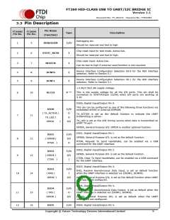
3.3 Pin Description
Pin Name
FT260Q
Pin No.
FT260S
Pin No.
Type
I/O
I
Description
(Function)
DEBUGGER
Debugging pin.
1
5
6
7
Should be reserved and tied to high
Chip reset input for test mode. Active low.
Should be reserved and tied to high.
2
3
STEST_RSTN
RESETN
Chip reset input. Active low.
I
Can be tied to high if external reset function is not required.
Device Interface Configuration Selection bit-0 for the HID interface
selection. Refer to Section 5.1
4
5
8
9
DCNF0
DCNF1
I
I
Device Interface Configuration Selection bit-1 for the HID interface
selection. Refer to Section 5.1
+3.3V/2.5V/1.8V supply voltage.
This is the supply voltage for all the I/O ports. This pin shall be
connected to VOUT3V3(pin 22/26) when I/O ports are working at
3.3V
6
10
VCCIO
P **
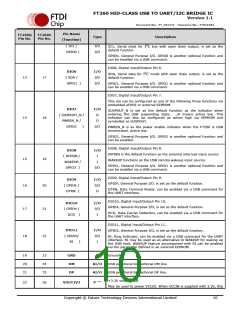
DIO0, Digital Input/Output Pin 0.
This pin can be configured as one of the following three functions via
embedded eFUSE or external EEPROM.
DIO0
( TX_ACTIVE /
TX_LED /
GPIOA
I/O
O
TX_ACTIVE is set as the default function to indicate the UART
transmitting is active.-
7
11
O
TX_LED is set as the LED driving source when data is transmitted on
UART TX port.
)
I/O
GPIOA, General Purpose I/O. GPIOA is another optional function.
DIO1, Digital Input/Output Pin 1.
DIO1
I/O
I/O
O
GPIOB, General Purpose I/O. is set as the default function.
8
9
12
13
( GPIOB /
RTSN, Request To Send Handshake, can be enabled via
command for the UART interface.
a USB
RTSN
)
DIO2, Digital Input/Output Pin 2.
DIO2
I/O
I/O
I
GPIOE, General Purpose I/O. is set as the default function.
( GPIOE /
CTSN, Clear To Send Handshake, can be enabled via a USB command
for the UART interface.
CTSN
)
DIO3, Digital Input/Output Pin 3.
DIO3
I/O
I
RXD, Receive Asynchronous Data Input, is set as default function
when the UART interface is selected via {DCNF1, DCNF0}.
10
14
( RXD /
GPIOC )
I/O
GPIOC, General Purpose I/O, is set as the default function when UART
interface is not configured.
DIO4, Digital Input/Output Pin 4.
DIO4
I/O
O
TXD, Transmit Asynchronous Data Output, is set as default when the
UART interface is selected via {DCNF1, DCNF0}.
11
12
15
16
( TXD /
GPIOD )
I/O
GPIOD, General Purpose I/O, is set as default when the UART
interface is not configured.
DIO5
I/O
DIO5, Digital Input/Output Pin 5.
Copyright © Future Technology Devices International Limited
9

 FTDI [ FUTURE TECHNOLOGY DEVICES INTERNATIONAL LTD. ]